
Method Capable of Preventing Mistakenly Triggering a Touch panel

a technology of touch panel and triggering method, which is applied in the direction of instruments, computing, electric digital data processing, etc., can solve the problems of error signal, difficult to write on the touch panel, and the inability of the touch panel to rest on the touch panel

Inactive Publication Date: 2010-03-04
ETURBOTOUCH TECH
View PDF4 Cites 43 Cited by
  • Summary
  • Abstract
  • Description
  • Claims
  • Application Information

AI Technical Summary

Problems solved by technology

Since palm rejection is not available in a projected capacitive touch panel, when a device is held to write on a medium or large projected capacitive touch panel, the palm cannot rest on the touch panel, making it difficult to write on the touch panel.
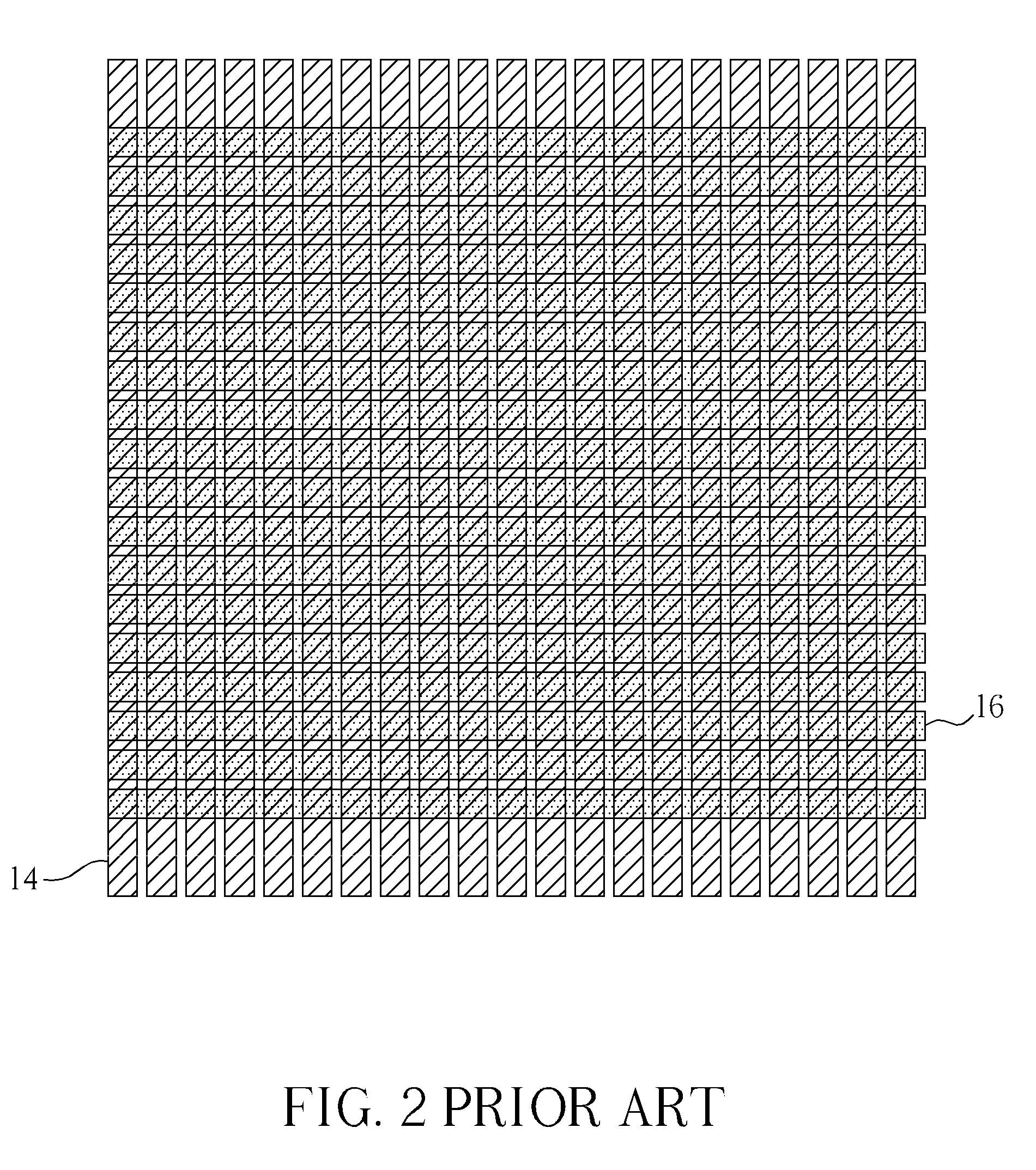
Then when a finger or stylus enters a formal input, the matrix multi-point touch panel becomes unable to identify the input of the finger or stylus thereby generating an error signal.
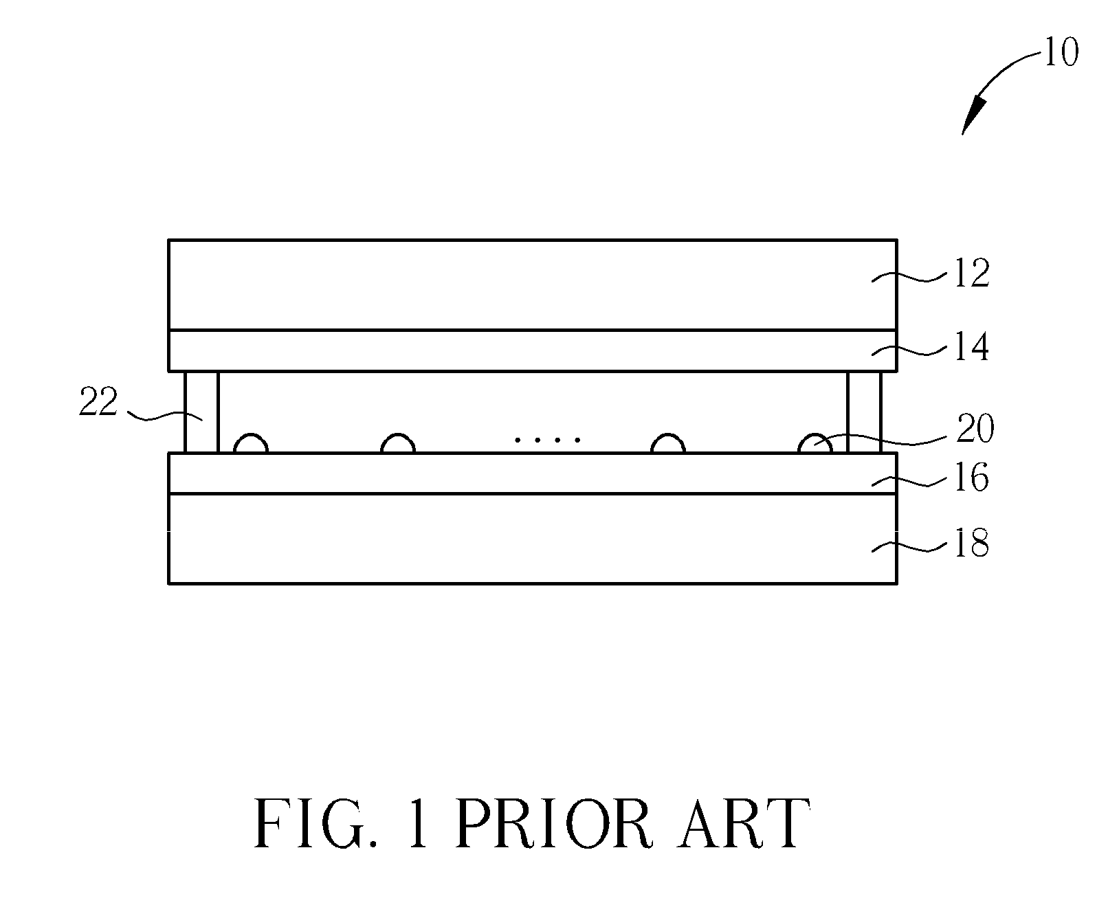
However this makes the finger or stylus difficult to trigger the touch panel 10 and reduces the sensitivity of the touch panel 10.

Method used


Image

  • Method Capable of Preventing Mistakenly Triggering a Touch panel
  • Method Capable of Preventing Mistakenly Triggering a Touch panel
  • Method Capable of Preventing Mistakenly Triggering a Touch panel

Examples


first embodiment

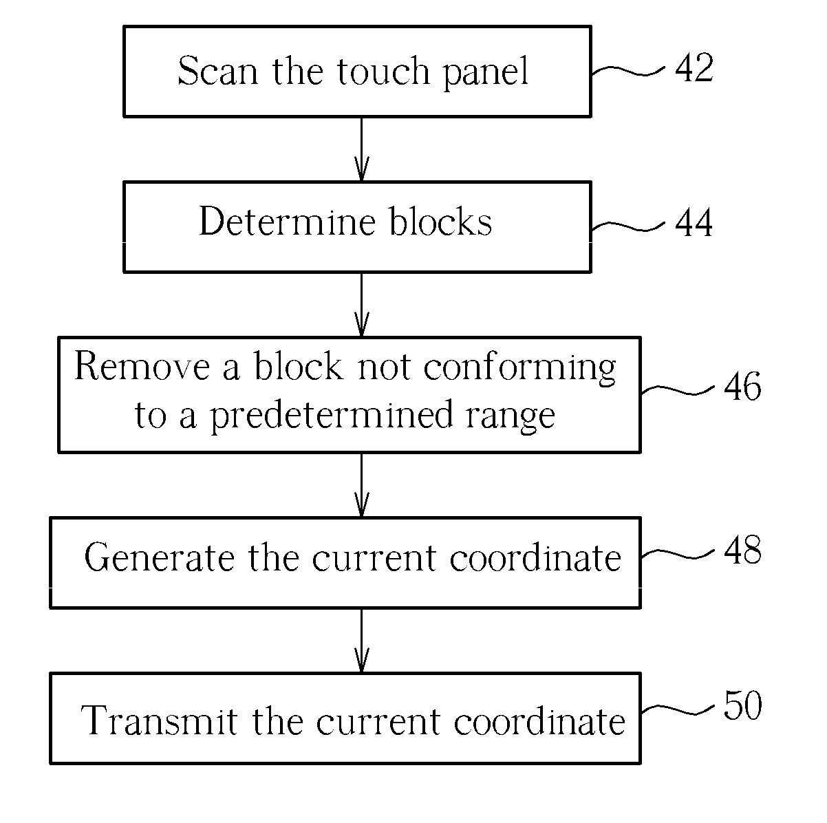
[0024]For instance, in the first embodiment, it can be determined that if the length of a block in either X or Y direction exceeds 5 intersecting points of X-directional electrodes 68 and Y-directional electrodes 70, then the block will be removed because it is triggered by the palm. Contrarily, if the length of a block in neither X nor Y direction exceeds 5 intersecting points of X-directional electrodes 68 and Y-directional electrodes 70, then the block will be treated as triggered by the finger. Since the length of the second block 26 in X direction exceeds 5 intersecting points of X-directional electrodes 68 and Y-directional electrodes 70, Step 46 will remove the second block 26 regardless whether the length of the second block 26 in Y direction exceeds 5 intersecting points of X-directional electrodes 68 and Y-directional electrodes 70 or not. Since the length of the first block 24 in neither X nor Y direction exceeds 5 intersecting points of X-directional electrodes 68 and Y-...

second embodiment

[0025]In the second embodiment, it can be determined that if the length of a block in X direction is not shorter than 5 intersecting points of X-directional electrodes 68 and Y-directional electrodes 70, or if the length of the block in Y direction exceeds 5 intersecting points of X-directional electrodes 68 and Y-directional electrodes 70, then the block will be removed because it is triggered by the palm. Contrarily, if the length of a block in X direction is shorter than 5 intersecting points of X-directional electrodes 68 and Y-directional electrodes 70, and the length of the block in Y direction does not exceed 5 intersecting points of X-directional electrodes 68 and Y-directional electrodes 70, then the block will be treated as triggered by the finger. Since the length of the second block 26 in X direction is not shorter than 5 intersecting points of X-directional electrodes 68 and Y-directional electrodes 70, Step 46 will remove the second block 26 regardless whether the leng...


PUM


Abstract

To perform palm rejection, scan a plurality of areas on a touch panel to detect a plurality of triggered areas within the plurality of areas. Then detect which of the triggered areas are next to one another to determine a plurality of blocks. If the plurality of blocks contain a block with an overlarge area, then eliminate the block with the overlarge area, and generate a current coordinate according to a block with a smaller area which may be triggered by a finger or stylus.

Description

BACKGROUND OF THE INVENTION[0001]1. Field of the Invention[0002]The present invention relates to a palm rejection method, and more particularly, a method capable of preventing mistakenly triggering a touch panel.[0003]2. Description of the Prior Art[0004]There are many prior art multi-point touch techniques for triggering a touch panel. One of the common techniques is matrix multi-point touch such as projected capacitive touch. A projected capacitive touch panel can be triggered by a finger, a stylus, or a conductor held by a hand, etc. When writing on a medium or large touch panel, a portion of a palm is often rested on the touch panel. Thus a technique called palm rejection is developed when writing on a resistive multi-point touch panel. Since palm rejection is not available in a projected capacitive touch panel, when a device is held to write on a medium or large projected capacitive touch panel, the palm cannot rest on the touch panel, making it difficult to write on the touch ...

Claims


Application Information

Patent Timeline
IPC IPC(8): G06F3/041
CPCG06F3/0488G06F3/0418
Inventor WU, MING-TSUNGWU, CHENG-KO
Owner ETURBOTOUCH TECH
Learn More