
Portable seating device

a seating device and portability technology, applied in the field of seating devices, can solve the problems of straining and/or aggravated upper and/or lower back, lack of backrest on these bleachers, and prolonged sitting on these bleachers for extended periods, etc., to achieve convenient adjustment and/or maneuverability, reduce drawbacks, and facilitate back mechanics

Inactive Publication Date: 2010-02-25
LEE GORDON J +3
View PDF11 Cites 13 Cited by
  • Summary
  • Abstract
  • Description
  • Claims
  • Application Information

AI Technical Summary

Benefits of technology

[0005]In view of the foregoing, an objective of the present invention is to provide an improved portable seating device that eliminates or at least generally reduces the drawbacks of the above-mentioned conventional seats. More particularly, an important objective of the present invention is to provide an improved portable seating device that is conducive to back mechanics. Another important objective of the present invention is to provide an improved portable seating device that is capable of providing user-specific back support. Yet another objective is to provide a portable seating device that is easily adjustable and / or maneuverable. Still another important objective is to provide a portable seating that is light-weight and / or easy to transfer / carry. These objectives and additional advantages are generally realized by the present invention, which generally relates to a portable seating device, such as, for example, a portable stadium seat.
[0006]The portable seating device of the present invention generally includes a seat and a first backrest movably interconnected with the seat. Herein, “portable,”“portability,” and the like, generally refer to a characteristic of the seating device of the present invention which enables the same to be freely moved and / or easily / conveniently transported about by a potential user. Accordingly, the portable seating device may be said to be totable. In other words, a potential user may be able to carry a portable seating device of the invention with him / her “by hand,” or by using an appropriate handle, shoulder strap, backpack, and / or carry-case. So, for example, “portable” may refer to the seating device weighing no more than about 10 pounds in one embodiment, no more than about 7 pounds in another embodiment, and no more than about 5 pounds in yet another embodiment.

Problems solved by technology

Regardless of the various materials utilized to construct these bleachers, sitting on these bleachers for extended periods of time can be extremely uncomfortable.
Moreover, the lack of a backrest on these bleachers may tend to strain and / or aggravate the upper and / or lower back.
Further, while some spectator event facilities are equipped with individual seats having backrests, these individual seats tend to be made of metal, hard plastics and / or wood, which have also tended to contribute to similar user discomfort and / or aggravation.
As a result, many people desiring to attend spectator events have foregone such attendance due to the discomfort and / or physical demands associated with sitting on bleachers or hard seats.
Moreover, such user discomfort / aggravation has also been associated with sitting on bench-style or hard seats associated with picnic tables, boats, hunting stands (e.g., for deer hunting), and the like.
While these cushions may address the pain of sitting on the hard surface (at least to a limited extent), they do not address strain on the upper and lower back.
Although some of these portable seats have at least somewhat of a solid backrest, some of these portable seats are equipped with backrests that are extremely flimsy (e.g., provide a backrest in form, but not in substance) so that user back pain / strain is still a common occurrence.
While some portable seats have provided limited substantive relief of back pain / strain associated with sitting in bleachers or the like, one of the costs associated with the same is that these portable seats tend to be extremely heavy, which may make them difficult to transport and / or even unusable for certain (e.g., elderly and / or physically weak) individuals.

Method used


Image

  • Portable seating device
  • Portable seating device
  • Portable seating device

Examples


Embodiment Construction

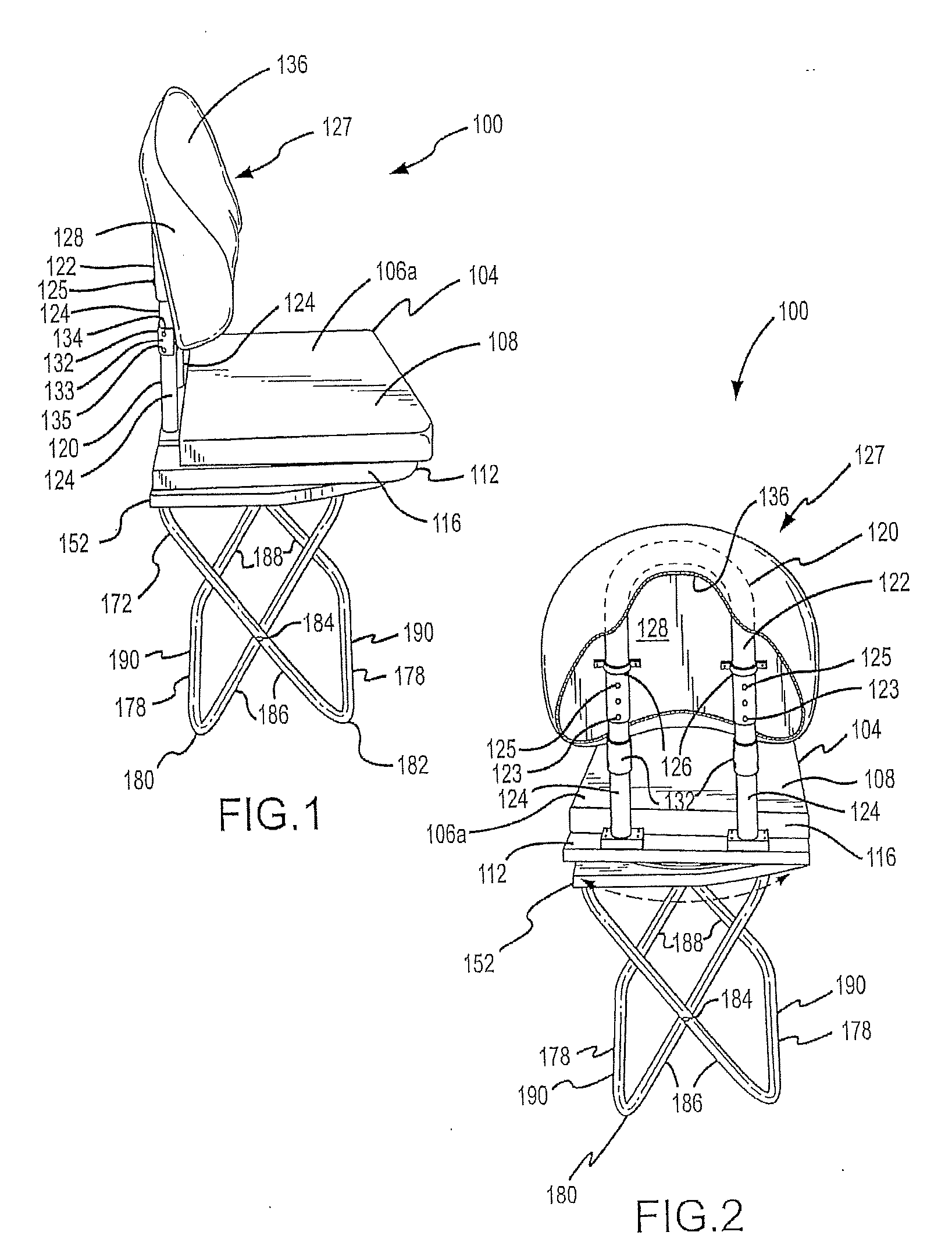
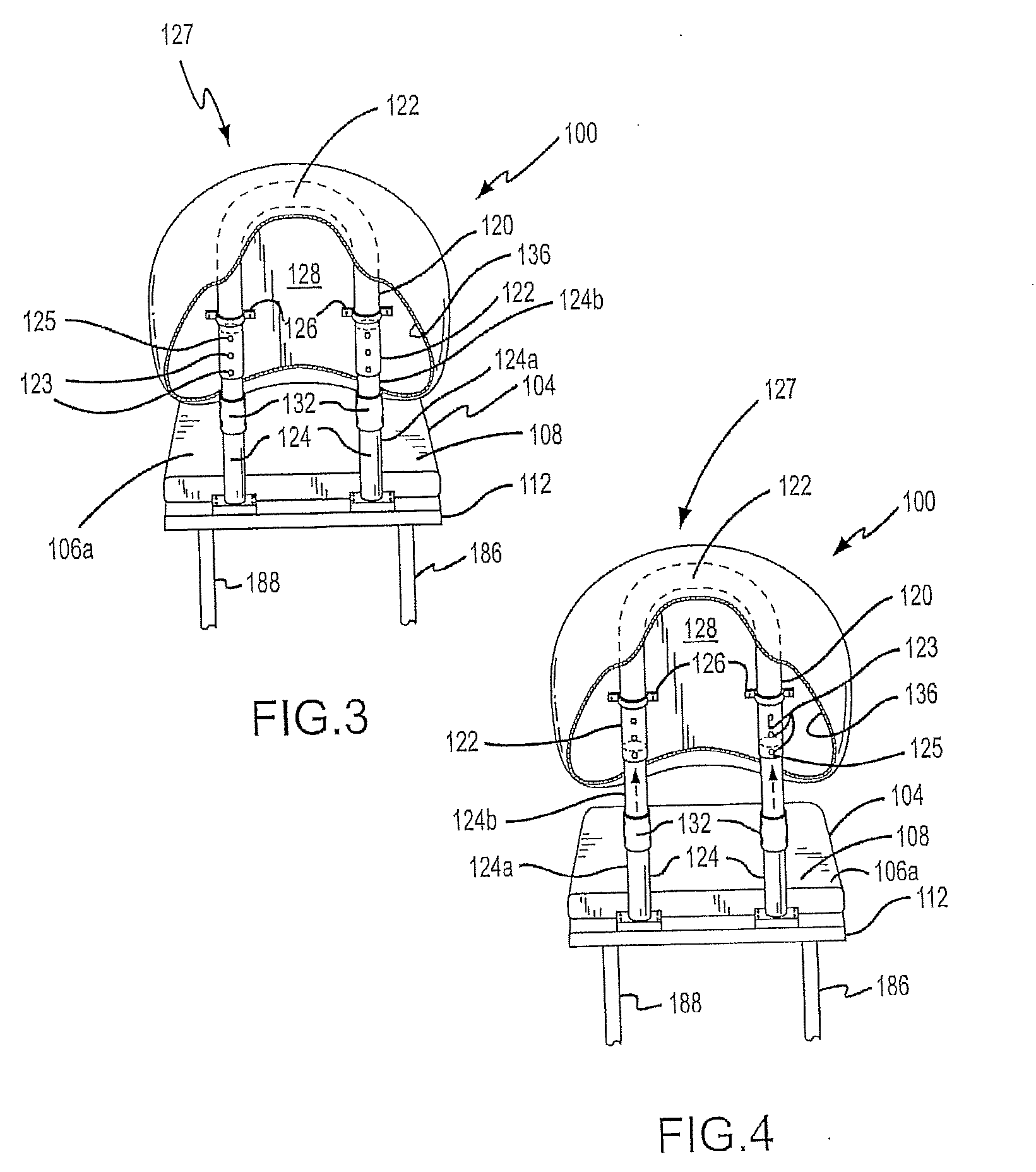
[0062]The present invention will now be described in relation to the accompanying drawings that at least assist in illustrating its various pertinent features. FIGS. 1-2 illustrate one embodiment of a portable seating device 100. Primary components of the portable seating device 100 are a seat 104 that is movably interconnected with a base 152, a stand 172 that is preferably detachably interconnected with the base 152 in any appropriate manner to dispose the seat 104 a desired distance above the subject supporting surface (e.g., a floor, the ground), a collapsible frame 120, and a backrest assembly 127 that is movably interconnected with the frame 120. The ability to detach the stand 172 from the base 152, along with the ability to collapse the frame 120 relative to the seat 104, contribute to the portability / transportability of the portable seating device 100. Various comfort-related features are included in the portable seating device 100. For instance, the seat 104 rotates or swi...


PUM


Abstract

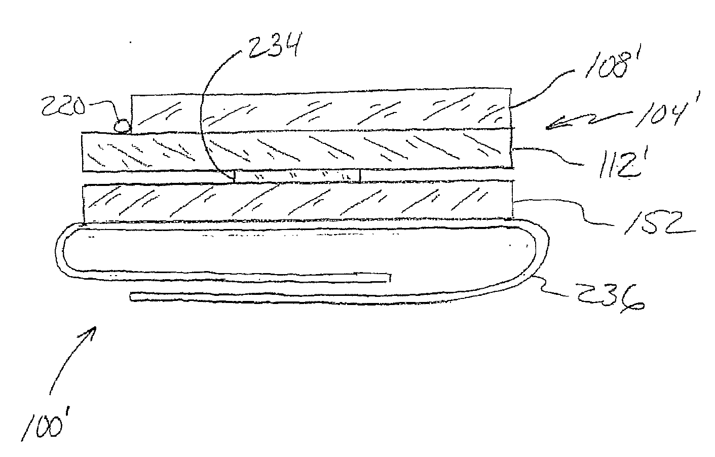
A portable seating device (100′) is disclosed that has a seat (104′) with one or more internal storage compartments (224 / 230). The seat (104′) includes an upper seat section (108′) that may be pivoted away from a platform (112′) to access one or more storage compartments (224) on a lower surface of the upper seat section (108′) and to access one or more storage compartments (230) on an upper surface of the platform (112′). The platform (112′) is rotatably interconnected with a base (152). A backrest assembly (127) is appropriately interconnected with the seat (104′), and a stand (172) is detachably interconnected with the base (152) to accommodate multiple configurations for the portable seating device (100′). Preferably, the backrest assembly (127) is movable between stowed and deployed positions, and includes one or more adjustment features when in its deployed position.

Description

CROSS-REFERENCE TO RELATED APPLICATIONS[0001]This patent application is a continuation of U.S. patent application Ser. No. 11 / 551,342, that was filed on Oct. 20, 2006, and that is entitled “PORTABLE SEATING DEVICE,” which is a continuation-in-part of U.S. patent application Ser. No. 10 / 465,802, that was filed on Jun. 19, 2003, and that is entitled “PORTABLE SEATING DEVICE,” and further claims priority to U.S. Provisional Patent Application Ser. No. 60 / 747,188, that was filed on May 13, 2006, and that is entitled “PORTABLE SEATING DEVICE.” The entire disclosure of each of the above-noted patent applications is hereby incorporated by reference herein, and priority is claimed to each of these three patent applications as well.FIELD OF THE INVENTION[0002]The present invention generally relates to seating devices and, more particularly, to a portable seating device usable under multiple seating conditions, such as in conjunction with a bench-style or hard seating system.BACKGROUND OF THE...

Claims


Application Information

Patent Timeline
Patent Type & Authority Applications(United States)
IPC IPC(8): A47C13/00
CPCA47C7/407A47C7/402
Inventor LEE, GORDON J.MOLINA, CRISTOBALLEE, PAUL J.CARLSON, DAVID L.
Owner LEE GORDON J
Learn More