
Method and apparatus for fitting grips

a technology of tubular grips and fitting devices, which is applied in the field of methods and fitting devices for grips, can solve the problems of damage to the rubber grip, inability to accurately control the resultant position of the grip, and difficulty in applying the tubular grip to the handle, so as to reduce friction

Inactive Publication Date: 2009-12-24
SCHELL MARK
View PDF16 Cites 5 Cited by
  • Summary
  • Abstract
  • Description
  • Claims
  • Application Information

AI Technical Summary

Benefits of technology

[0009]means for carrying a tubular grip over a handle and being adapted to fit between the tubular grip and the handle to reduce friction between the tubular grip and the handle and thereby enabling the tubular grip to slide onto the handle.
[0010]Enabling the grip to be slid onto the handle avoids the problems mentioned above associated with rolling the rolled-up grip onto the handle.
[0013]The elongate members of the carrying means preferably have a profile that, when fitted between the tubular grip and the handle, reduces the area of contact between the tubular grip and the handle and thereby reduces friction between the tubular grip and the handle to such an extent that the grip is able to slide onto the handle.
[0020]By maintaining such spacings, the elongate members are prevented from bunching. If bunching occurs, the elongate members only reduce the friction between the handle and grip in a localised region. In other regions where the grip is in contact with the handle, the friction may prevent the grip being slid onto the handle. In essence, the correct spacing of elongate members ensures sufficient friction reduction to enable the grip to be slid onto the handle.
[0025]The positioning means and elongate members preferably are co-operable for retaining the elongate members in a position ready to receive a grip for sliding the grip onto the handle. The co-operation of the positioning means and the elongate members enables the elongate members to be loaded sequentially into positioning means without the loaded elongate members moving from the ready position during loading of the remaining elongate members.

Problems solved by technology

While the friction that exists between a rubberised grip and a handle assists to prevent movement of the grip, the friction causes difficulty in applying the tubular grip to the handle.
Consequently, sliding a rubberised tubular grip onto the handle of a cricket bat, for instance, is extremely difficult and is likely to result in destruction of the rubber grip.
This approach suffers from not being able to accurately control the resultant location of the grip relative to the handle.
For instance, the rubber grip may cover too much or too little of the handle.
Once rolled onto the handle, the position of the grip on the handle can only be adjusted to a limited extent and with difficulty owing to the friction between the grip and handle.
This approach also suffers from the problem of forcing the rolled up grip over an enlarged end of the handle.
Rolling the rolled-up grip over the enlarged end is made more difficult by the fact that the rolled-up grip is harder to force over the enlarged end.

Method used


Image

  • Method and apparatus for fitting grips
  • Method and apparatus for fitting grips
  • Method and apparatus for fitting grips

Examples


Embodiment Construction

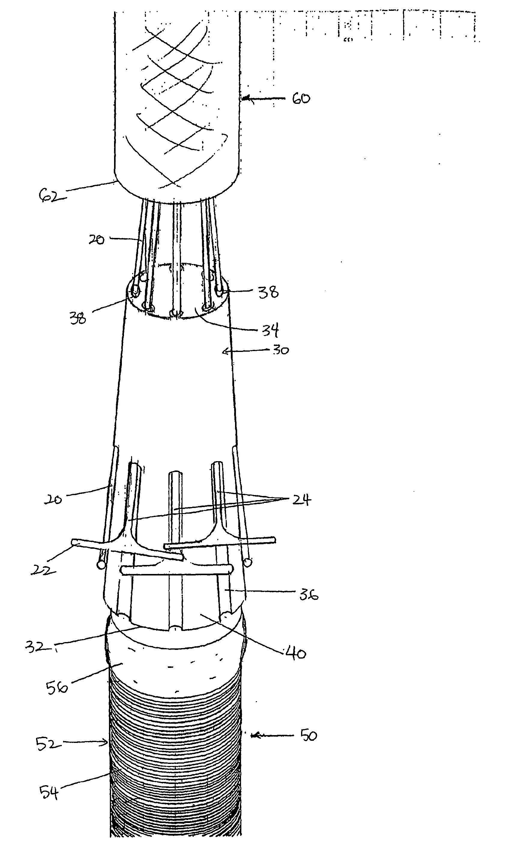
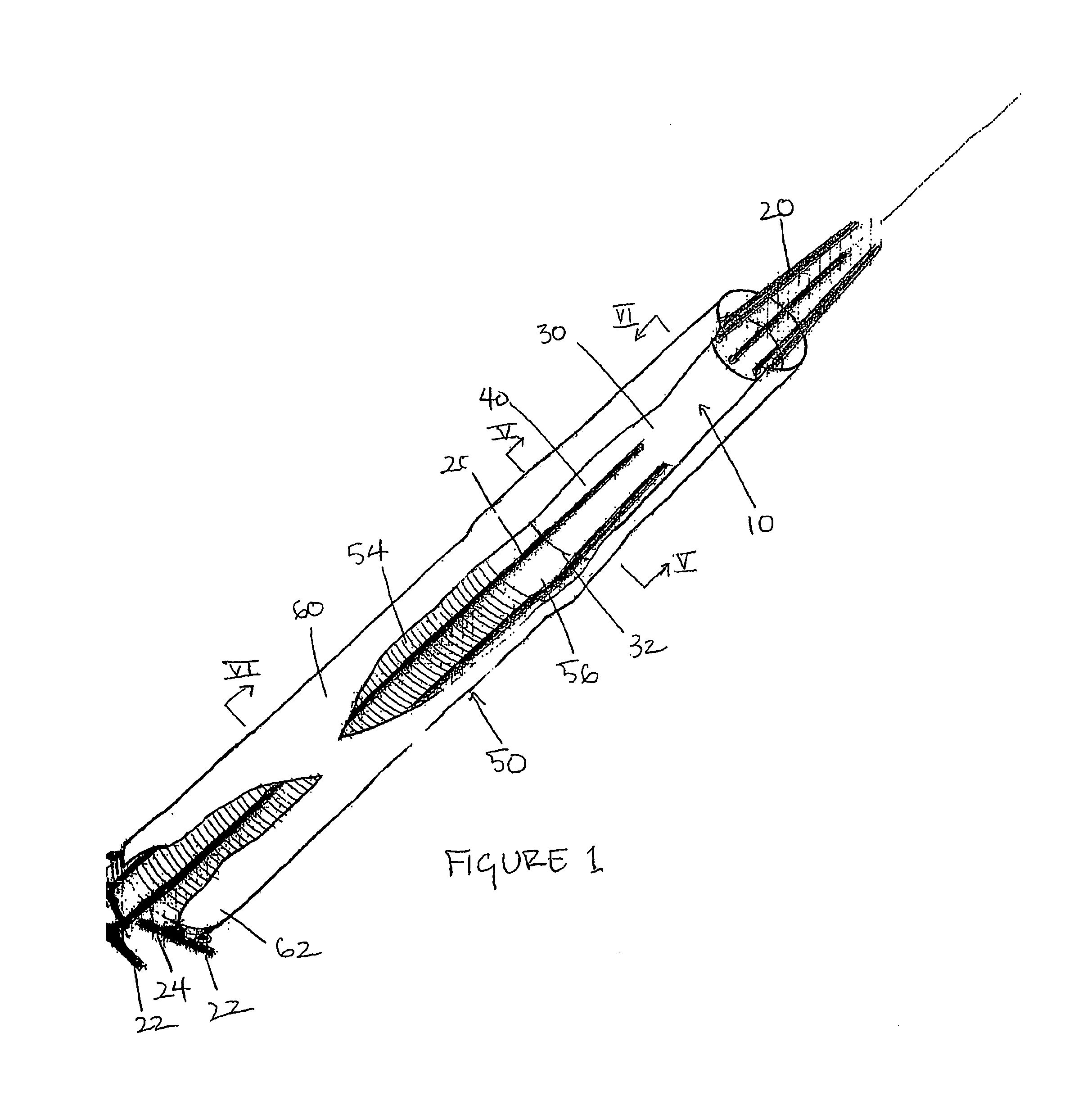
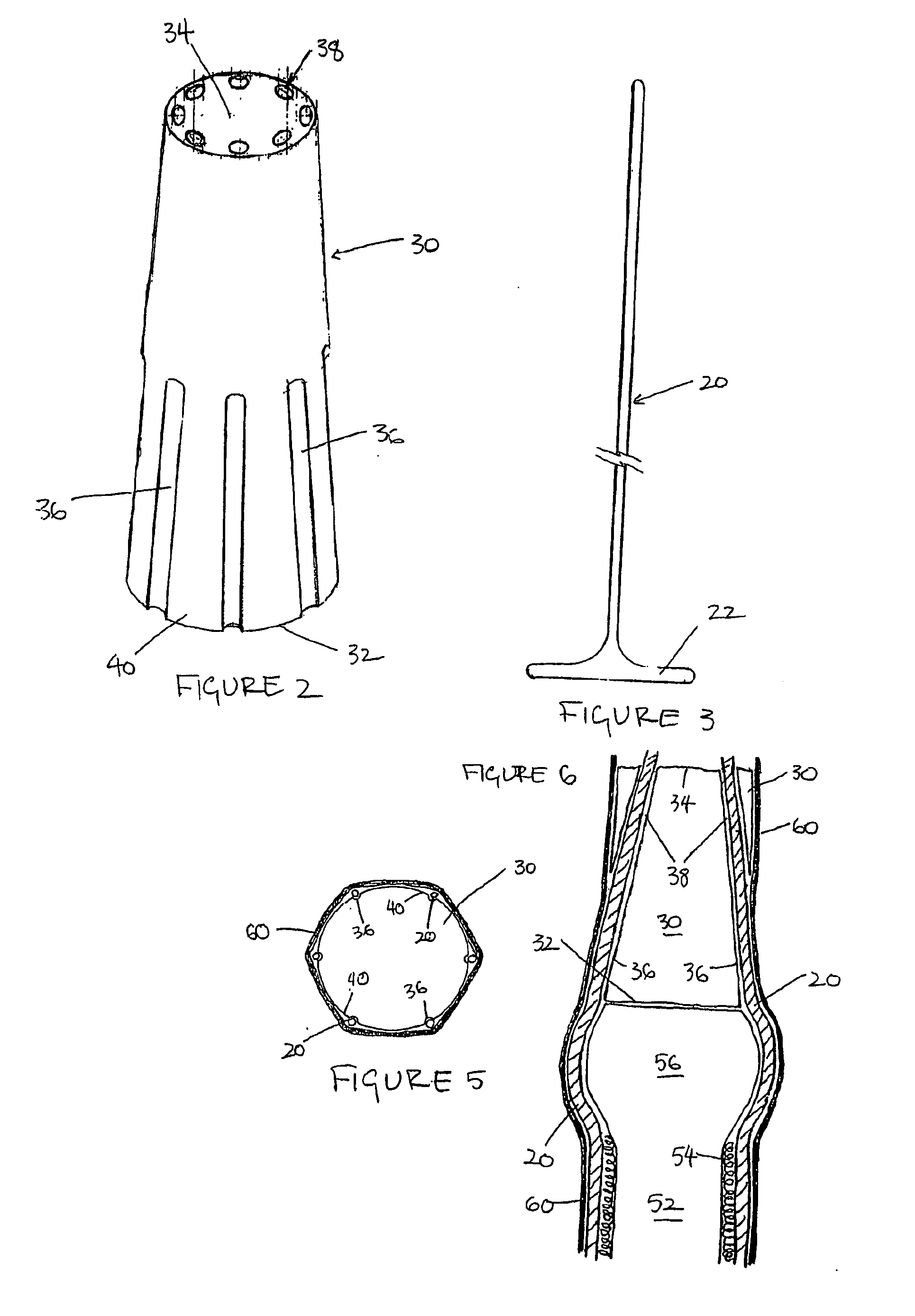
[0044]One embodiment of a grip fitting assembly 10 in accordance with the first aspect of the present invention is shown in FIGS. 1-6.

[0045]The assembly 10 comprises carrying means in the form of runners 20 and a positioning means in the form of body 30.

[0046]The runners 20 have a thin flexible body approximately 35 cm long and 2 mm wide. Each runner 20 has a handle 22 formed as a perpendicular extension from one end of each runner 20. Each handle 22 is formed to enable a user to pull on the handles collectively to pull a grip 60 onto a handle 50 and to enable a user to retract a runner 20 from between the grip 60 and the handle 50 once the grip 60 is located on the handle 50.

[0047]The body 30 has a generally frusto-conical form with a delivery end 32 and a free end 34.

[0048]Grooves 36 are formed in surface 40 of the body 30 and are linked to cavities or channels 38 that extend from the grooves 36 through the body 30 and open at the free end 34. The grooves 36 and channels 38 are ar...


PUM

PropertyMeasurementUnit
diameteraaaaaaaaaa
frictionaaaaaaaaaa
lengthaaaaaaaaaa

Abstract

The present invention relates to a method and apparatus for fitting grips to hand-held equipment, such as sporting equipment, for example cricket bats, by sliding a grip over the hand-held equipment. The apparatus comprises means that carries a tubular grip over a handle. The carrying means is adapted to fit between the handle and the grip to reduce friction between the handle and grip and thereby enable the grip to slide over the handle. The method of the present invention involves positioning the carrying means inside a grip, sliding the carrying means over the handle to slide the grip over the handle and removing the carrying means from between the grip and the handle.

Description

FIELD OF THE INVENTION[0001]The present invention relates to a method and apparatus for fitting grips to hand-held equipment to improve a user's control of the equipment. The invention has particular application to equipment having handles fitted with tubular grips. The present invention has particular, although not exclusive, application to sporting equipment, such as cricket bats.BACKGROUND OF THE INVENTION[0002]One known form of grip, used commonly with cricket bats, is a tubular grip or sleeve of rubber that fits over a handle. The grip is retained in position on the handle by friction with the underlying material, typically string bound around the handle. Furthermore, the handle is dimensioned slightly larger than the dimensions of the grip such that the grip is in an expanded state when fitted to the bat handle so the resilient nature of the rubber grip prevents or minimises the grip shifting on the handle in use.[0003]While the friction that exists between a rubberised grip a...

Claims


Application Information

Patent Timeline
Patent Type & Authority Applications(United States)
IPC IPC(8): B23P11/02B23P19/00
CPCA63B49/08A63B53/14A63B59/0014A63B59/0029Y10T29/4987A63B59/06A63B59/08A63B2059/0018Y10T29/53657A63B59/0077A63B60/48A63B59/55A63B2060/462A63B2102/20A63B60/10A63B60/06A63B60/08A63B60/14A63B2102/18A63B59/50A63B60/00
Inventor SCHELL, MARK
Owner SCHELL MARK
Learn More