
Actuator with actuating pin

Active Publication Date: 2009-12-10
TOYODA GOSEI CO LTD
View PDF6 Cites 12 Cited by
  • Summary
  • Abstract
  • Description
  • Claims
  • Application Information

AI Technical Summary

Benefits of technology

The present invention provides an actuator with an actuating pin that prevents gas leaks and allows the actuating pin to move backward quickly during actuation. The actuator includes a piston with the actuating pin, a squib that generates driving gas, and a cylinder case that holds the piston. A sealing ring is provided to seal the gap between the actuating pin and the cylinder case, and a presser plate is provided to regulate the backward movement of the sealing ring. The actuator prevents gas leaks and allows the actuating pin to move backward quickly during actuation.

Problems solved by technology

However, in the actuators disclosed in US 2002 / 0135166A and JP 2007-333044A, although an actuating pin is made to protrude from a through hole provided in a ceiling wall part of a cylinder case, because a seal member to perform sealing so as to block up a gap formed between the actuating pin and the through hole when the actuating pin is inserted through the through hole is not provided, it is difficult to ensure sufficient airtightness of the cylinder case, which has left room for improvement in the point that a driving gas is prevented from leaking and the actuating pin is made to rapidly move backward during actuation.

Method used


Image

  • Actuator with actuating pin
  • Actuator with actuating pin
  • Actuator with actuating pin

Examples


Embodiment Construction

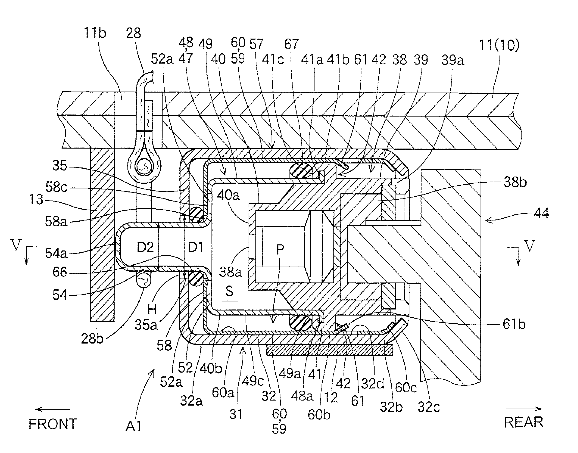
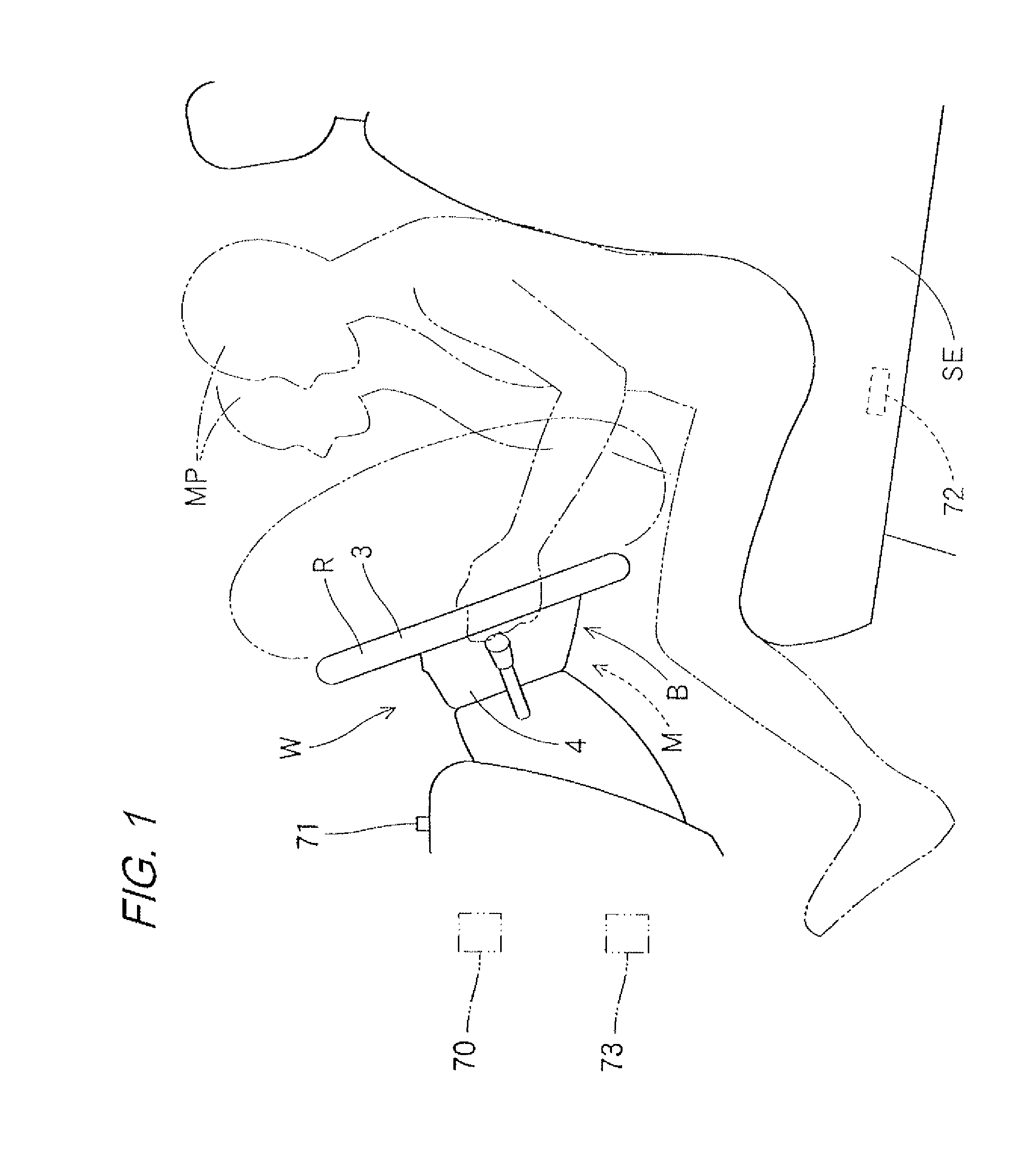
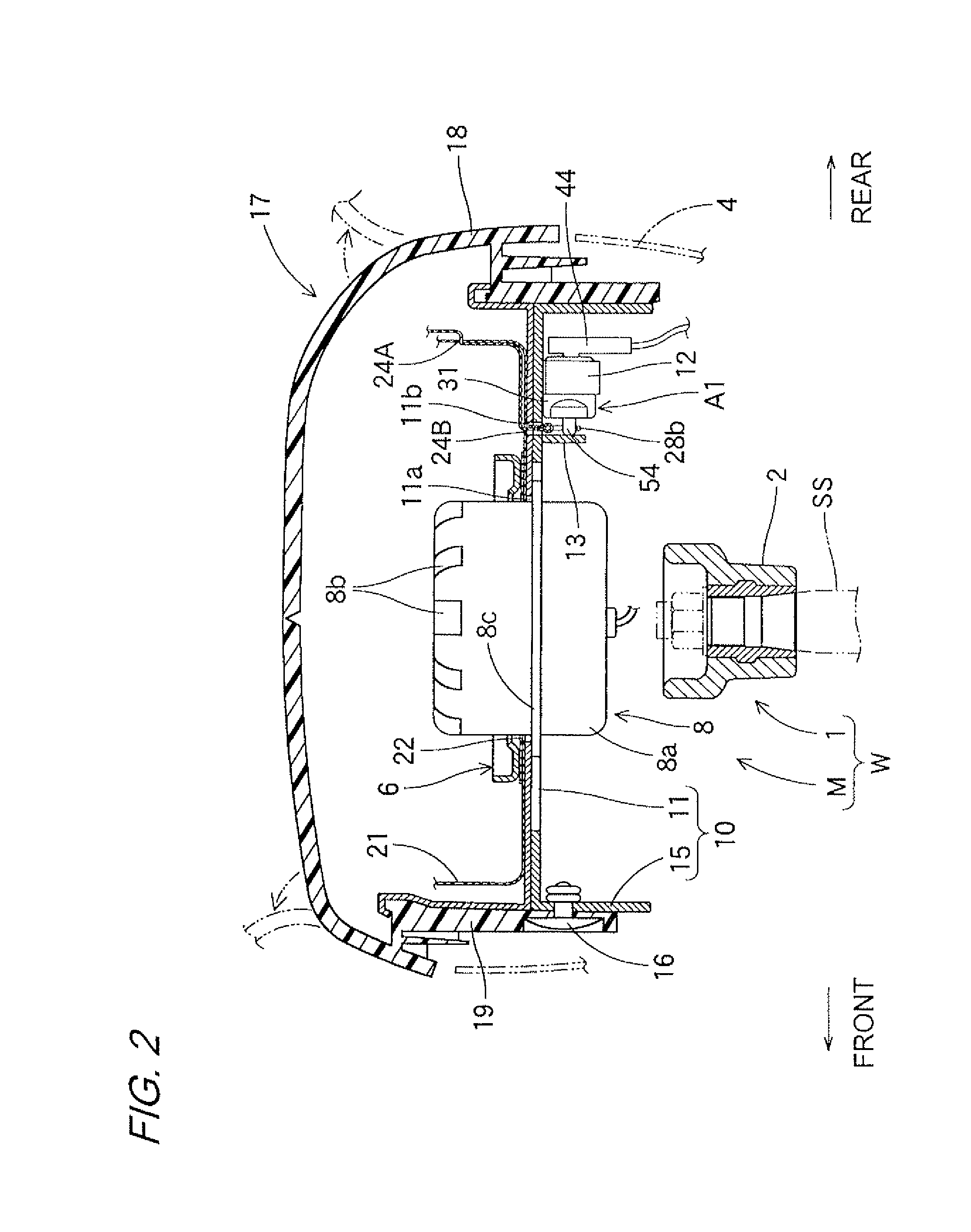
[0043]Hereinafter, one embodiment of the present invention will be described with reference to the drawings. An actuator A1 (refer to FIGS. 4 and 5) in the embodiment is installed in an airbag apparatus M mounted in a steering wheel W as shown in FIG. 1. The actuator A1 is configured such that its actuation along with an inflator 8 of the airbag apparatus M is controlled by a control device 70 shown in FIG. 1.

[0044]Note that the vertical and horizontal directions in the embodiment are based on the time when the steering wheel W which is mounted in a vehicle is steered straight-ahead unless otherwise noted. In the embodiment, the vertical and horizontal directions are shown such that a direction which is the same as the axial direction of a steering shaft SS (refer to the chain double-dashed line in FIG. 2) with which the steering wheel W is assembled, is set to the vertical direction, and a direction horizontally perpendicular to the axial direction of the steering shaft SS is set t...


PUM


Abstract

An actuator includes a piston having an actuating pin, a squib, and a cylinder case. The cylinder case has a peripheral wall part that covers the circumference of the piston and a ceiling wall part having a through hole which allows an actuating pin to protrude from the through hole. The actuator is configured to make the a piston move backward along with the actuating pin by ejecting a driving gas generated from the squib to a space between the ceiling wall part and the piston during actuation. A sealing ring which is relatively movable with respect to the actuating pin while maintaining the state of sealing up a gap between the actuating pin and the through hole, is provided at an inner face side of the ceiling wall part.

Description

BACKGROUND OF THE INVENTION[0001]1. Field of the Invention[0002]The present invention relates to an actuator which is movable so as to pull in an actuating pin along the axial direction during actuation, and to an actuator which is available for control for inner pressure in an airbag, the control for a shape of an airbag, and the like in an airbag apparatus which is mounted in, for example, a vehicle, that is required to instantly bring an actuating pin into action during actuation.[0003]2. Related Art[0004]Conventionally, there has been an actuator which is configured to let a piston held in a cylinder case so as to make an actuating pin protrude, move backward along with the actuating pin in the cylinder case with use of a driving gas generated when a squib provided in the piston is actuated. In this conventional actuator, the squib is configured to make the piston move backward along with the actuating pin by ejecting the driving gas to a space between the cylinder case and the ...

Claims


Application Information

Patent Timeline
Patent Type & Authority Applications(United States)
IPC IPC(8): B60R21/26B60R21/16B60R21/239F15B15/19
CPCB60R2021/23384B60R21/239
Inventor ITO, SHUNASAOKA, MICHIHISAISHIGURO, NAOHIKO
Owner TOYODA GOSEI CO LTD
Learn More