Input device and input method

a technology which is applied in the field of input device and input method, can solve the problems of insufficient contacts, inability to enter english alphabet, and inability to enter alphabetical characters, etc., and achieve the effect of significant practical value and simple operation

Inactive Publication Date: 2009-11-26
PANASONIC CORP
View PDF1 Cites 7 Cited by
  • Summary
  • Abstract
  • Description
  • Claims
  • Application Information

AI Technical Summary

Benefits of technology

[0027]As clarified out of the above description, an input device in the present invention can make an information inputting position stationary with respect to the device body since a first information group is rigidly assigned in each sections. Further, by rotating a rotor, a user can re-select different information from information corresponding to once specified section. Thus, the user can input desired information by simple operations even though the user presses a wrong button. Along with escalating miniaturization and multi-functionality among electronics devices, more and more users are likely to press wrong buttons on the electronics devices. Thus, the present invention is said to enjoy a significant practical value accordingly.

Problems solved by technology

The cellular phone disclosed in Patent Reference 1, however, is not capable of character entry.
In other words, even though the number of contacts provided at the end of the lever 604 is sufficient for entering the numbers 0 through 9, the contacts are insufficient for entering English alphabet, Japanese hiragana, or Japanese katakana.

Method used


Image

  • Input device and input method
  • Input device and input method
  • Input device and input method

Examples


first embodiment

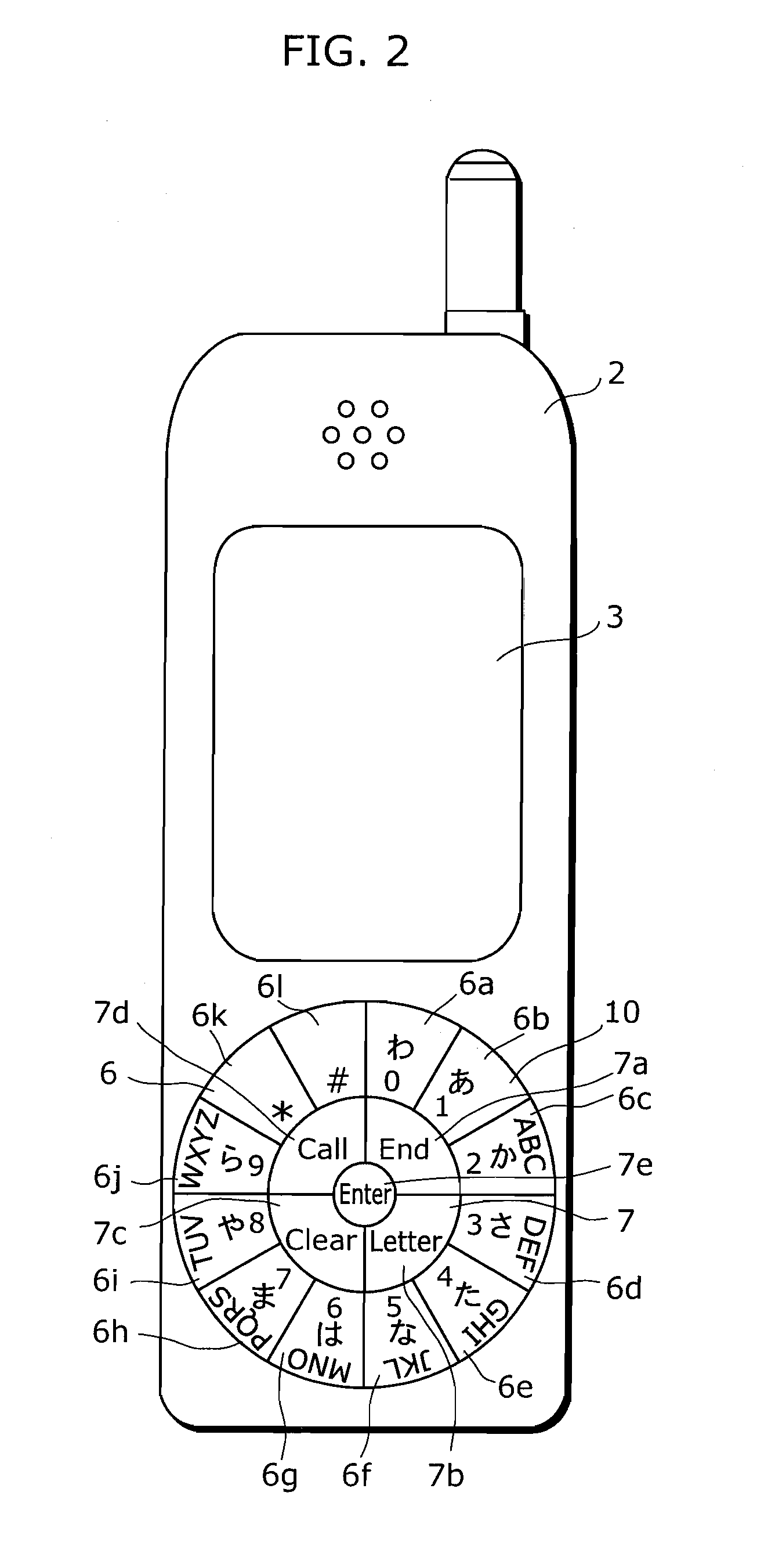
[0075]FIG. 3 is an elevation view of a cellular phone 201 applying an input device 203 in a first embodiment. As shown in FIG. 3, the cellular phone 201 includes a liquid crystal displaying unit 202 displaying various sets of information, a speaker unit 200 for a call, a microphone unit 204, and the input device 203 in the present invention. The input device 203 is located near the liquid crystal displaying unit 202 of the cellular phone, and is used for selecting and executing functions of the cellular phone 201 and entering symbols and characters.

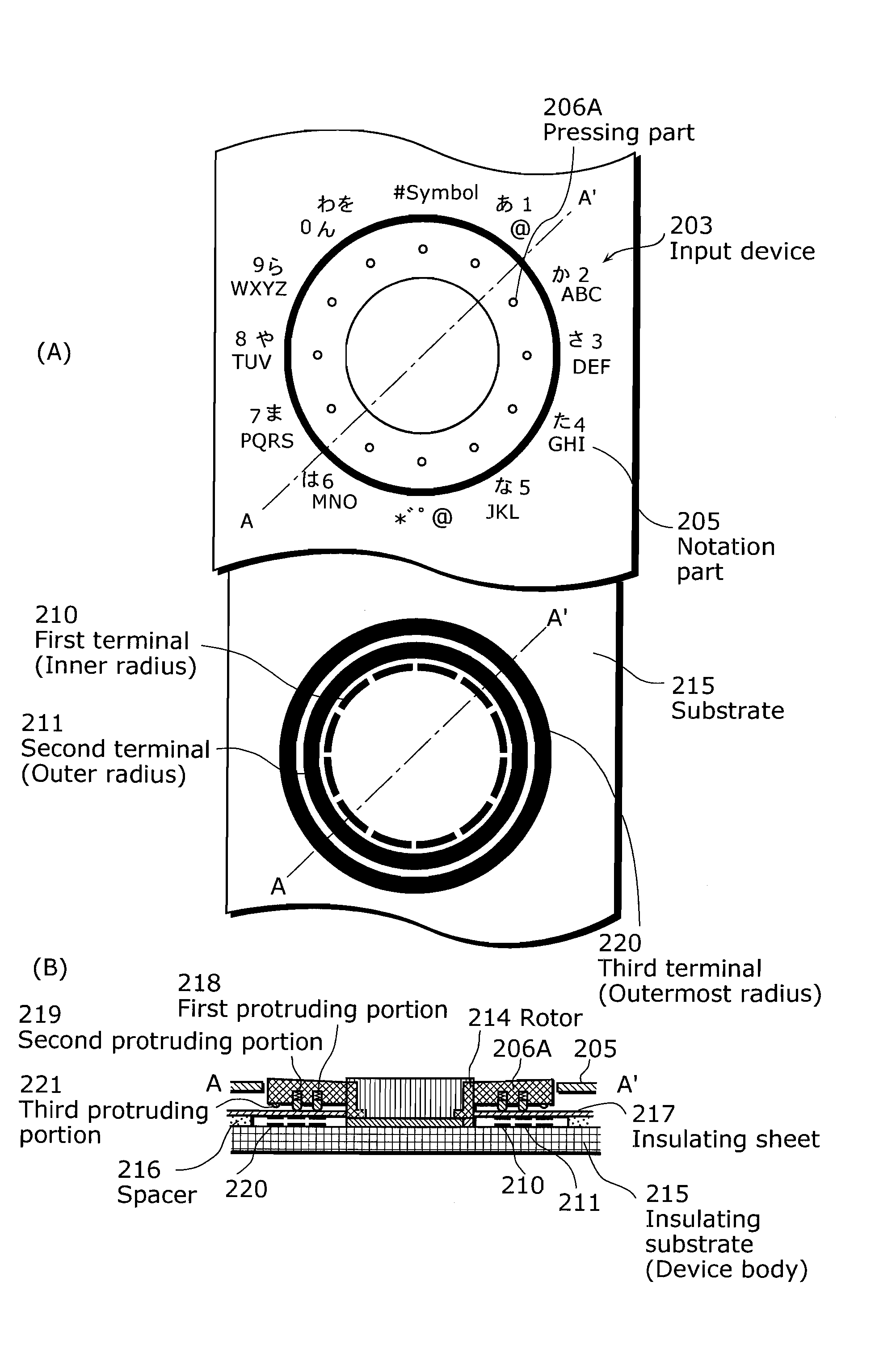
[0076]FIG. 4 are drawings showing internal structures of the input device 203. FIG. 4 (A) is an elevation view of an indicating part 205 on a casing surface, and an elevation view of a substrate 215 in the indicating part 205. FIG. 4 (B) is a cross-sectional view taken from line A-A′ of FIG. 4 (A). As shown in the drawings, the input device 203 includes: the indicating part 205; a pressing part 206A; a first terminal 210; a second termina...

second embodiment

[0129]In the first embodiment, a structure is described in that the rotation direction of the rotor 214 is not detected for selecting column characters. In the second embodiment, a structure is described in that the rotation direction of the rotor 214 is detected for selecting column characters.

[0130]FIG. 15 is a diagram conceptually illustrating a second information group in the second embodiment. FIG. 15 corresponds to FIG. 8 (B) in the first embodiment. The second embodiment is the same as the first embodiment in that the second information group is associated with primary information. Meanwhile, the second embodiment is different from the first embodiment in that the second embodiment adopts a structure to reflect the rotation direction of the rotor 214. The unit information sets included in the second information group are arranged inversely depending on the rotation direction. For a forward direction in which the rotation amount increases by 1, the sequence is adopted, and for...

third embodiment

[0135]In the first and second embodiments, a rotor in circle is exemplified; meanwhile, this rotor may be divided into some parts. In a third embodiment, a rotor divided into some parts is described. Hereinafter, the third embodiment shall be described, focusing on differences from the first embodiment.

[0136]FIG. 17 is the elevation view of the cellular phone 201 applying the input device 203 in the first embodiment. FIG. 18 illustrates an internal structure of the input device 203. FIG. 18 (A) is an elevation view of the indicating part 205 on a surface of a casing, and an elevation view of the substrate 215 in the indicating part 205. FIG. 18 (B) is a cross-sectional view taken from A-A′ of FIG. 18 (A).

[0137]As shown in the drawings, the input device 203 includes: the indicating part 205; a first pressing part 206; a second pressing part 207; a third pressing part 208; a fourth pressing part 209; the first terminal 210; the second terminal 211; the third terminal 220; the rotor 21...


PUM


Abstract

The present invention provides an input device which enables a user to input desired information by simple operations even though a user has pressed a wrong button, as well as to make an information inputting position stationary.The input device in the present invention includes: a rotor; a section specifying unit specifying a section; a rotation amount detecting unit detecting a rotation amount from the specified section; a section corresponding information holding unit which holds correspondence relationship between each of the sections and a unit of information corresponding to each of the sections; an information group holding unit which holds, as a first information group, each of units of information associated with the corresponding section; an information specifying unit specifying a unit of information corresponding to the specified section based on the held correspondence relationship between the section and the unit of information; and an information selecting unit selecting, out of the held first information group, a predetermined unit of information according to the rotation amount with respect to the specified unit of information as a reference point.

Description

TECHNICAL FIELD[0001]The present invention relates to input devices which input information, and particularly to an input device for in a portable personal computer, a cellular phone, a remote controller for an electronic device, and a portable audio-visual appliance.BACKGROUND ART[0002]More and more electronics devices are downsizing with a variety of functions, which increases needs for easy-to-operate user interfaces in order for a user to input a lot of information. In particular, widespread cellular phones usually include pre-installed e-mail functions transmitting and receiving character information, in addition to communication functions. The cellular phones are even equipped with music reproduction functions, TV broadcasting receiving functions, and WWW browsing functions. Even though a user interface, integrating these functions and having a high input efficiency, is desired, user interfaces with currently common cellular phones are still a push-button type in which push bu...

Claims


Application Information

Patent Timeline
Patent Type & Authority Applications(United States)
IPC IPC(8): G06F3/03G06F3/0487G06F3/0489H04M1/72469
CPCG06F3/0362H04M1/23H04M2250/70H04M1/72583H04M2250/22H04M1/233H04M1/72469
Inventor INOUE, SHIGEYUKIYAMAMOTO, HIROSHITAKASAKI, SHINICHI
Owner PANASONIC CORP
Why Eureka
Try Eureka