
Lane marker recognizing apparatus

a technology of lane marker recognition and apparatus, which is applied in the field oflane marker recognition apparatus, can solve the problem of false recognition of the image portion of the lane marker, and achieve the effect of improving the recognition accuracy of the stud-type lane marker

Inactive Publication Date: 2009-10-29
HONDA MOTOR CO LTD
View PDF8 Cites 21 Cited by
  • Summary
  • Abstract
  • Description
  • Claims
  • Application Information

AI Technical Summary

Benefits of technology

[0007]An object of the present invention is to provide a lane marker recognizing apparatus, a vehicle, and a lane marker recognizing program which could improve recognition accuracy of the stud-type lane markers discretely provided on a road.
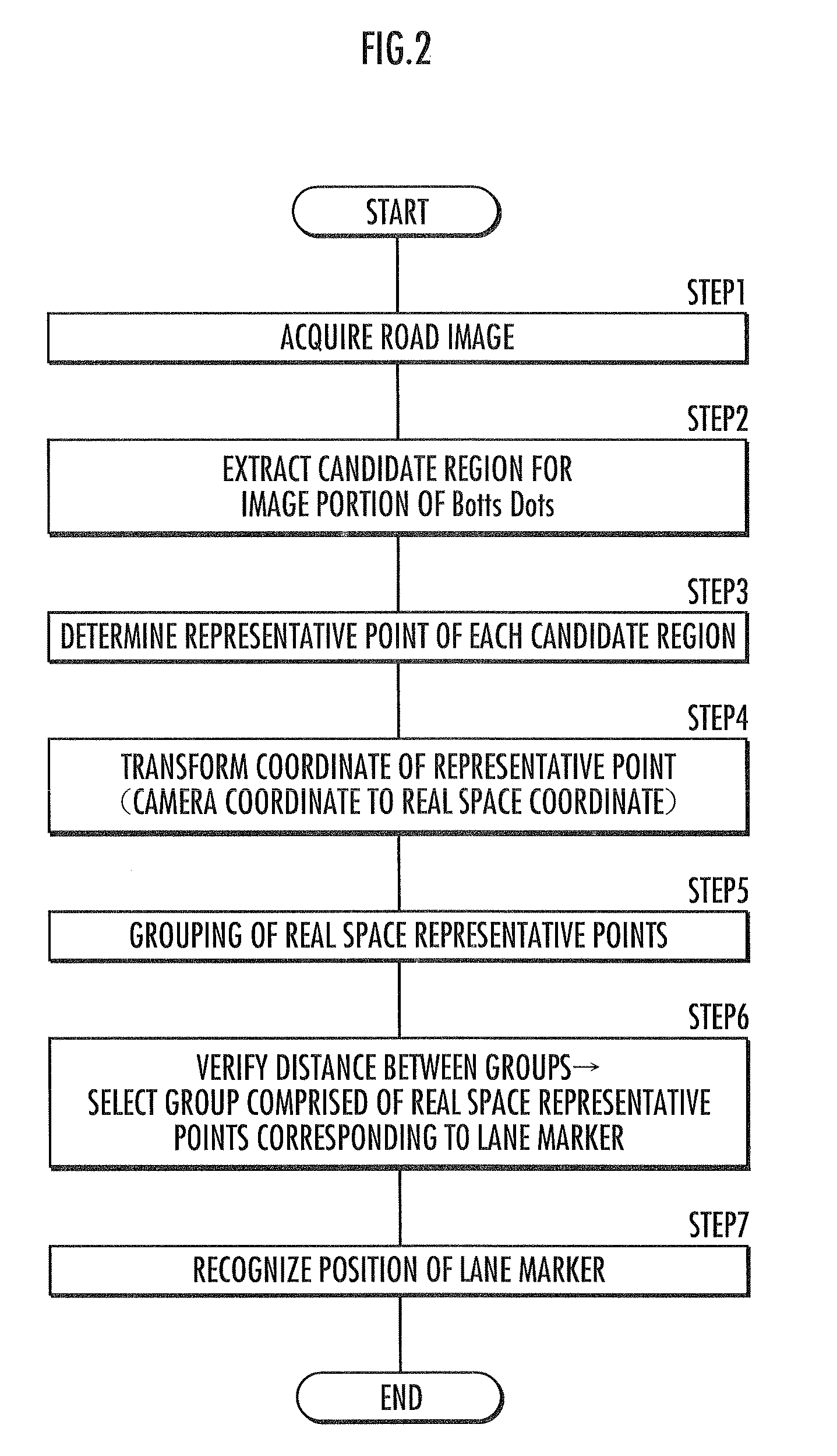
[0011]On the other hand, those real space representative points not included in the group has high possibility of being the position of objects or the like other than the lane marker. Thus, by recognizing the position of the lane marker with the lane marker position recognizing means on the basis of the real space representative points formed into one group by the grouping means, the position of the lane marker can be recognized with good accuracy, while preventing position of objects other than lane marker from being erroneously identified as the position of the lane marker.
[0013]According to this invention, the representative points are grouped by the grouping means on condition that three or more representative points aligned in the same direction exists, therefore the case where the lane marker position is recognized on the basis of the real space representative point which has no consistency in its directionality and has low possibility of being the position of the lane marker may be prevented.
[0015]According to this invention, because the lane markers are provided in a linear fashion or in a curved fashion, it is assumed that the real space representative points calculated on the basis of the image portion of the lane marker are scattered in a linear fashion or in a curved fashion. Therefore, by obtaining the polynomial equation of a predetermined order which approximates a dot sequence of the real space representative points formed into one group by the grouping means to a straight line or a curved line, and calculating the coefficient of determination which is the coefficient indicating the degree of approximation of the dot sequence of the representative points by the polynomial equation with the coefficient of determination calculating means, the lane marker position recognizing means recognizes the position of the lane marker on the basis of a plurality of the real space reference points constituting the group having the coefficient of determination equal to or greater than a predetermined value, so that the recognition accuracy of the position of the lane marker may be improved by excluding the groups comprised of real space representative points having low linearity or curvilinearity.
[0017]According to this invention, the stud-type lane markers discretely provided are generally defined so that groups comprised of a predetermined number of lane markers provided at a predetermined interval are arranged at a predetermined interval. Therefore, in the case where there exists a plurality of groups having the same number of the real space representative points constituting the group and the distance between the centroid of the groups is equal to or greater than the first threshold and is less than the second threshold, the lane marker position recognizing means recognizes the position of the lane markers on the basis of the real space representative points constituting such plurality of the groups. By doing so, the position of the lane marker may be determined more accurately by excluding the real space representative point on the basis of the image portion other than the lane marker.
[0024]According to the present invention, as with the lane marker recognizing apparatus according to the present invention explained above, by recognizing the position of the lane marker with the lane marker position recognizing means on the basis of the real space representative points formed into one group by the grouping means, the position of the lane marker can be recognized with good accuracy, while preventing position of objects other than lane marker from being erroneously identified as the position of the lane marker.

Problems solved by technology

The use of the pattern matching technique, however, has a problem in that when there are objects of a shape similar to the reference shape for pattern matching exists on the road, there is a fear that the same is falsely recognized as the image portion of the lane marker.

Method used


Image

  • Lane marker recognizing apparatus
  • Lane marker recognizing apparatus
  • Lane marker recognizing apparatus

Examples


Embodiment Construction

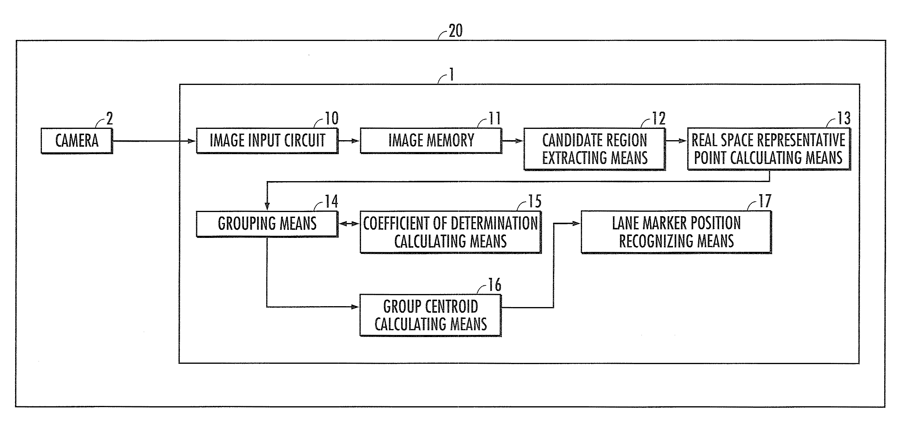
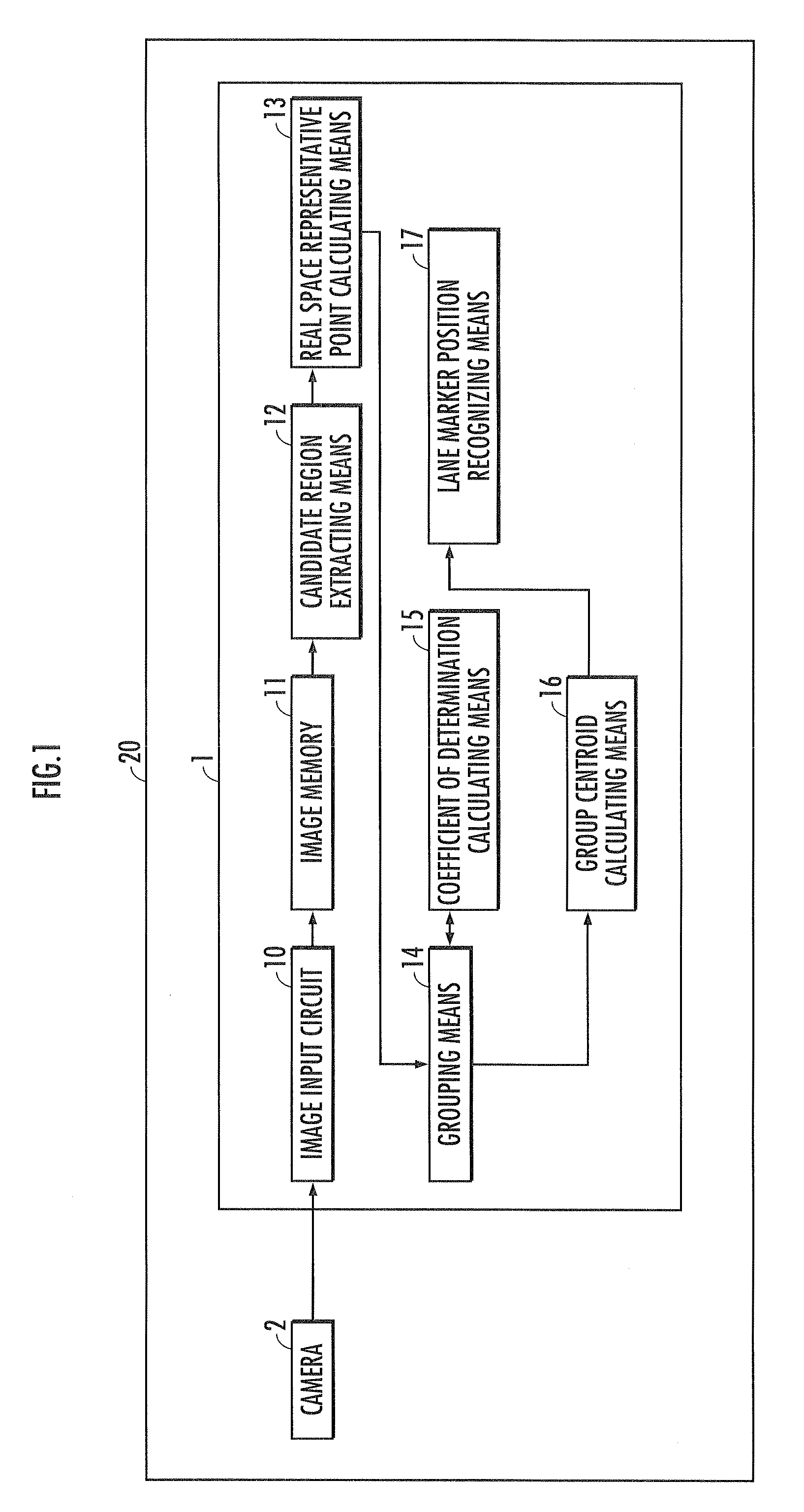
[0035]An example of a preferred embodiment of the present invention will now be described with reference to FIGS. 1 through 7. With reference to FIG. 1, a lane marker recognizing apparatus 1 is used by being mounted on a vehicle 20 (a vehicle of the present invention), and recognizes the position of the Botts Dots (corresponds to a stud-type lane marker of the present invention) discretely provided on a road for dividing the traffic lane, from a road image acquired by a camera 2 (corresponds to an imaging means of the present invention) which takes an image of the road ahead of the vehicle.

[0036]The lane marker recognizing apparatus 1 is an electronic unit constituted from a microcomputer (corresponds to a computer of the present invention) or the like, and the microcomputer functions as a candidate region extracting means 12, a real space representative point calculating means 13, a grouping means 14, a coefficient of determination calculating means 15, a group centroid calculating...


PUM


Abstract

A lane marker recognizing apparatus which recognizes stud-type lane markers from acquired road image includes a candidate region extracting means for extracting a region having the possibility of being an image portion of the lane marker, from the road image, as a lane marker candidate region, a real space representative point calculating means for determining a representative point of the lane marker candidate region according to a predetermined condition, and calculating a real space position corresponding to the representative point as a real space representative point, a grouping means for forming one group of the real space candidate points having a relative distance within a predetermined range set according to standards on the lane marker, and a lane marker position recognizing means for recognizing the position of the lane marker based on the real space representative point formed into one group by the grouping means.

Description

BACKGROUND OF THE INVENTION[0001]1. Field of the Invention[0002]The present invention relates to a lane marker recognizing apparatus, a vehicle, and a lane marker recognizing program having a function of recognizing stud-type lane markers discretely provided on a road.[0003]2. Description of the Related Art[0004]Conventionally, there is known a lane marker recognizing apparatus which recognizes lane markers for dividing a traffic lane provided on a road on the basis of an image data acquired by an in-vehicle camera which captures an image of the road ahead of the vehicle. As the lane markers provided on the road, there are used linear lane markers such as lane boundary lines (white lines) and stud-type lane markers which are discretely provided such as Botts Dots (Nonretroreflective Raised Pavement Marker) or cat's eyes (Retroreflective Raised Pavement Marker).[0005]Note that the linear lane markers can be detected by a straight line extraction technique such as a Hough transform wh...

Claims


Application Information

Patent Timeline
IPC IPC(8): H04N7/18
CPCG06K9/00798G06V20/588
Inventor MORI, NAOKI
Owner HONDA MOTOR CO LTD
Learn More