Method and Apparatus for Simulating Consumer Electronic Control Functionality for Devices

a technology of consumer electronic control and simulating device, which is applied in the direction of instruments, television systems, computing, etc., can solve the problems of many hdmi peripheral devices that have not been designed to comply with or otherwise make use of cec protocol, and the connected display device will be unable to properly d

Inactive Publication Date: 2009-10-01
SONY CORP +1
View PDF11 Cites 41 Cited by
  • Summary
  • Abstract
  • Description
  • Claims
  • Application Information

AI Technical Summary

Benefits of technology

The patent describes methods and devices for simulating the functionality of peripheral devices, such as CEC, using an HDMI switch. The switch has ports for connecting to peripheral devices and a display device. The switch's processor receives information about the peripheral devices and detects which port is active. The processor then sends the information about the active port to the display device using the HDMI communication protocol. The peripheral device does not need to communicate using the HDMI protocol. The technical effect of this invention is to enable the use of peripheral devices that do not communicate using the HDMI protocol, making it easier to develop and test new technology.

Problems solved by technology

The problem with this approach is that, in order to switch from one media source to another (e.g., from DVD to PVR), a user has to essentially remember which input is associated with which media source, or scroll through each and every one of the various available inputs until the desired input has been selected.
Unfortunately, many HDMI peripheral devices have not been designed to comply with or otherwise make use of the CEC protocol.
In such cases, the connected display device will be unable to properly detect the type of connected peripheral device, and instead will only be able to display the generic name of the input, as is the case with all non-HDMI devices.

Method used


Image

  • Method and Apparatus for Simulating Consumer Electronic Control Functionality for Devices
  • Method and Apparatus for Simulating Consumer Electronic Control Functionality for Devices
  • Method and Apparatus for Simulating Consumer Electronic Control Functionality for Devices

Examples


Embodiment Construction

Disclosure Overview

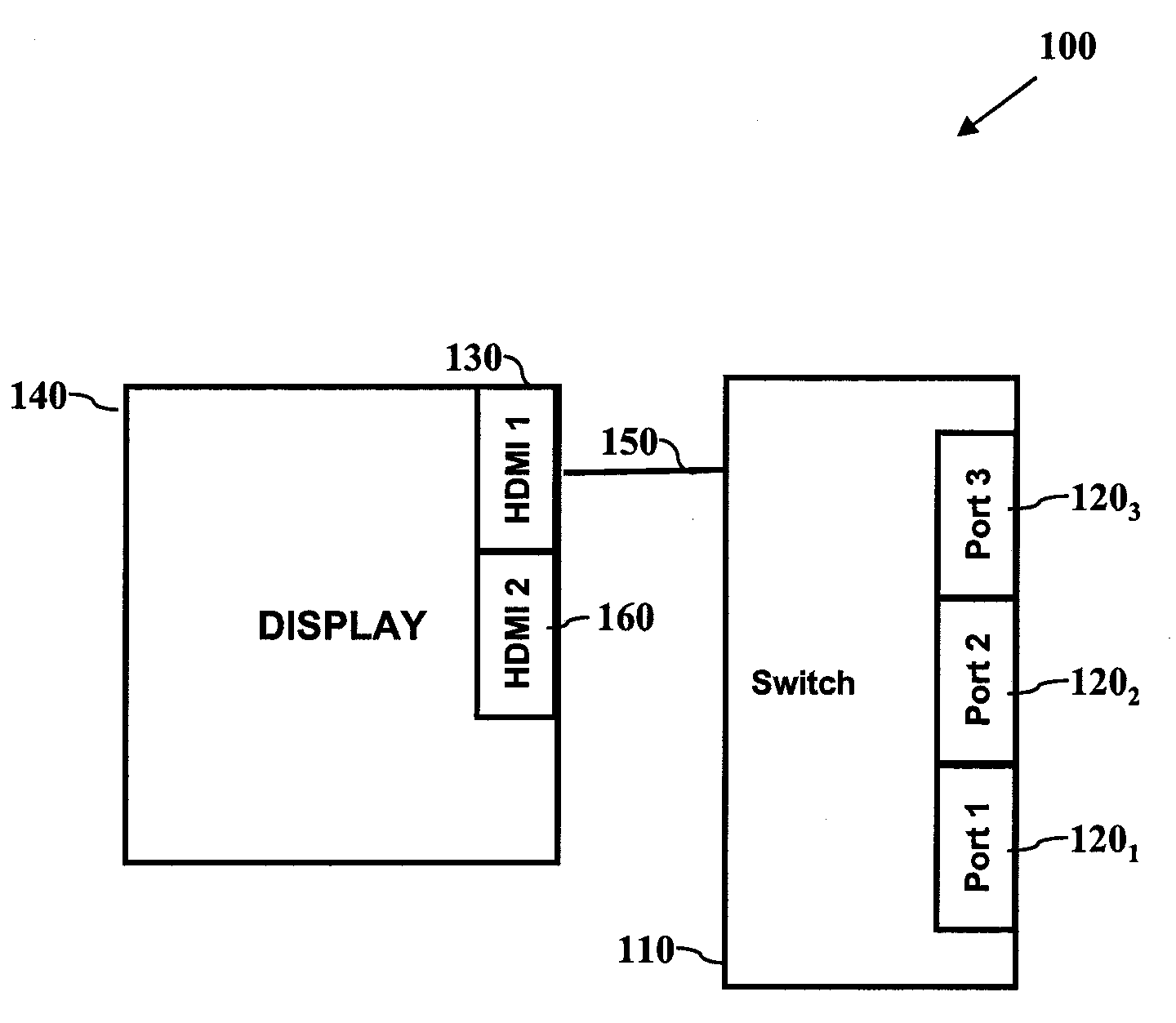
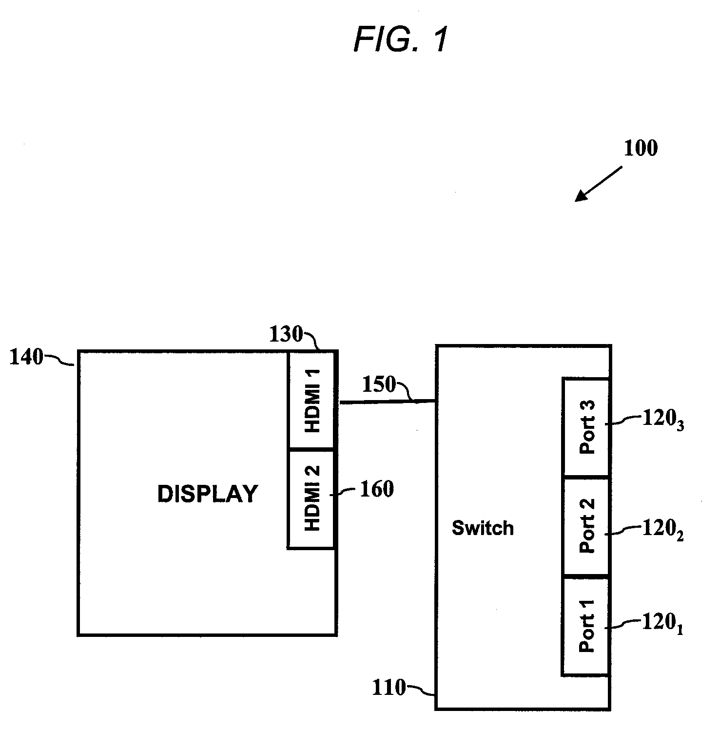
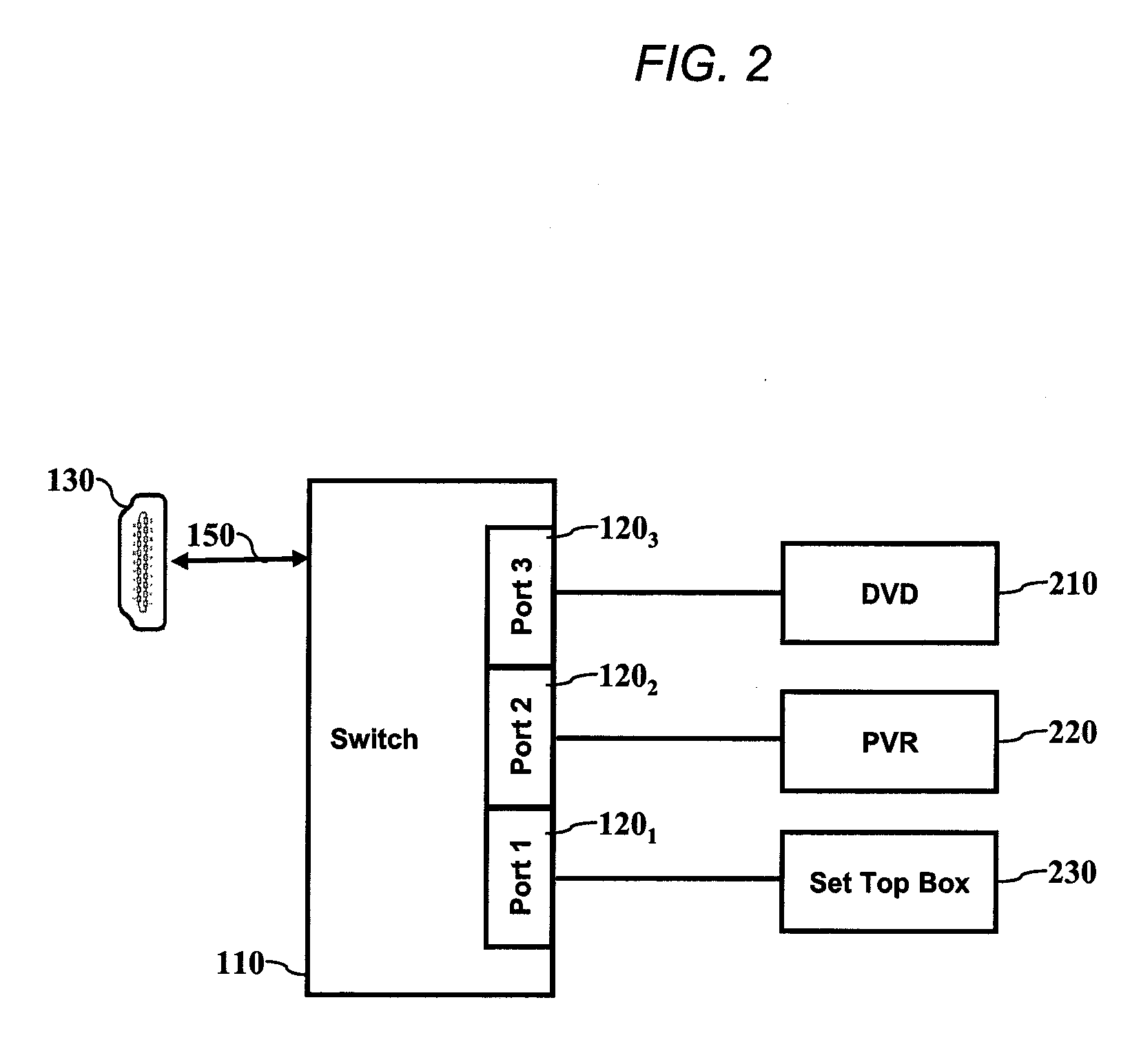
[0014]One aspect of the present disclosure relates to an HDMI switch, which includes a plurality of peripheral device ports, each of which may be coupled to a corresponding peripheral device. The switch may also include a display device port for coupling to a display device. In one embodiment, the switch is configured to receive device identification information from one or more of the peripheral devices coupled to the peripheral device ports and to detect which of the peripheral device ports is an active port. The switch may then transmit the device identification information for the peripheral device coupled to the active port to a display device in accordance with an HDMI communication protocol, such as the consumer electronic control (CEC) protocol. In one embodiment, the peripheral device coupled to the active port is not configured to communicate according to the HDMI communication protocol.

[0015]As used herein, the terms “a” or “an” shall mean one or more t...


PUM


Abstract

A High-Definition Multimedia Interface (HDMI) switch includes a plurality of peripheral device ports, each of which may be coupled to a corresponding peripheral device. The switch also includes a display device port for coupling to a display device. In one embodiment, the switch is configured to receive device identification information from one or more of the peripheral devices coupled to the peripheral device ports and to detect which of the peripheral device ports is an active port. The switch may then transmit the device identification information for the peripheral device coupled to the active port to a display device in accordance with an HDMI communication protocol, such as the consumer electronic control (CEC) protocol. In one embodiment, the peripheral device coupled to the active port is not configured to communicate according to the HDMI communication protocol.

Description

FIELD OF THE INVENTION[0001]The present invention relates in general providing or simulating consumer electronic control (CEC) functionality to non-CEC devices.BACKGROUND[0002]It is now typical for a user's home entertainment system to be made up of several peripheral consumer electronic devices, such as digital set top boxes (STBs), personal video recorders (PVRs), digital video disk (DVDs) and so on. These components are most often coupled to a single display, which is itself configured to select any one of its various available inputs at the touch of a button. Modern displays tend to ascribe a generic name to each such input, such as “Input 1,”“Input 2,” etc. The problem with this approach is that, in order to switch from one media source to another (e.g., from DVD to PVR), a user has to essentially remember which input is associated with which media source, or scroll through each and every one of the various available inputs until the desired input has been selected.[0003]With t...

Claims


Application Information

Patent Timeline
Patent Type & Authority Applications(United States)
IPC IPC(8): G06F3/00
CPCG09G5/006G09G2370/12H04N5/44513H04N21/485H04N21/4108H04N21/43615H04N21/43635H04N7/104H04N21/47
Inventor HIRONAKA, TAKASHICOLSEY, NICKSHINTANI, PETERBOYDEN, DAVIDDOMUKAI, TORU
Owner SONY CORP
Why Eureka
Try Eureka