
Photographic apparatus

a technology of photoelectric equipment and movable platforms, applied in the field of photoelectric equipment, can solve the problems of preventing accurate translation, and limiting the movable range of movable platforms in the x and y directions, so as to achieve the effect of performing both rotational and translational movements effectively

Inactive Publication Date: 2009-10-01
PENTAX RICOH IMAGING CO LTD
View PDF18 Cites 30 Cited by
  • Summary
  • Abstract
  • Description
  • Claims
  • Application Information

AI Technical Summary

Benefits of technology

[0012]Therefore, an object of the present invention is to provide a photographic apparatus that performs both the rotational and translational movements effectively.

Problems solved by technology

However, the rotational movement of the movable platform for the third stabilization limits the movable ranges of the movable platform in the x and y directions available to translational movement (the first and second stabilizations).
When the movable ranges of the movable platform available for the translational movement are limited, the translational movement cannot be performed accurately.
Conversely, the translational movement limits the movable ranges of the movable platform for rotational movement, thus preventing it from being performed accurately.

Method used


Image

  • Photographic apparatus
  • Photographic apparatus
  • Photographic apparatus

Examples


Embodiment Construction

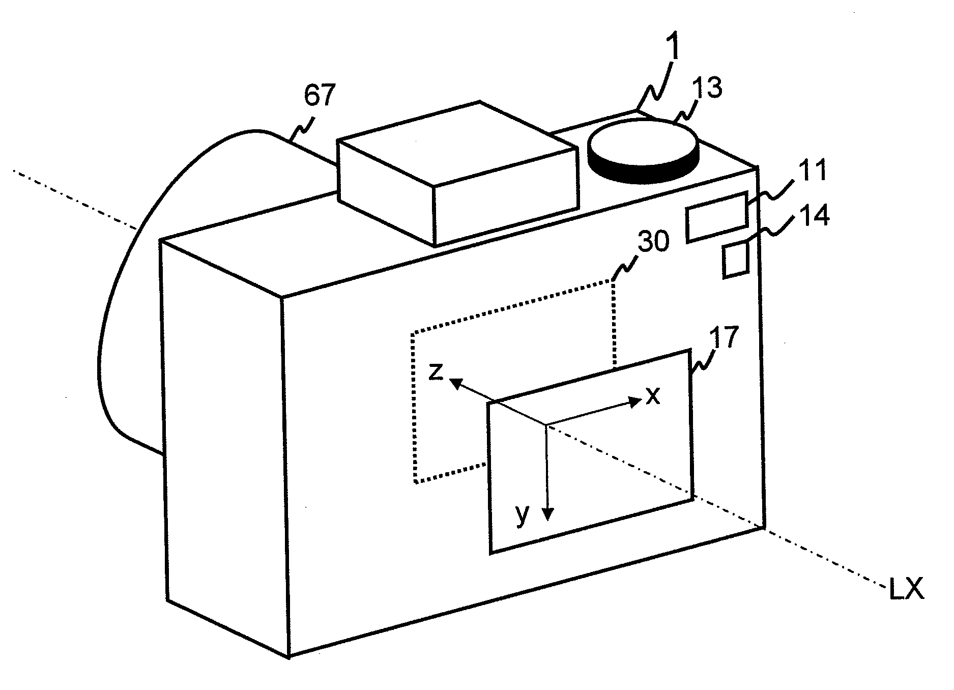
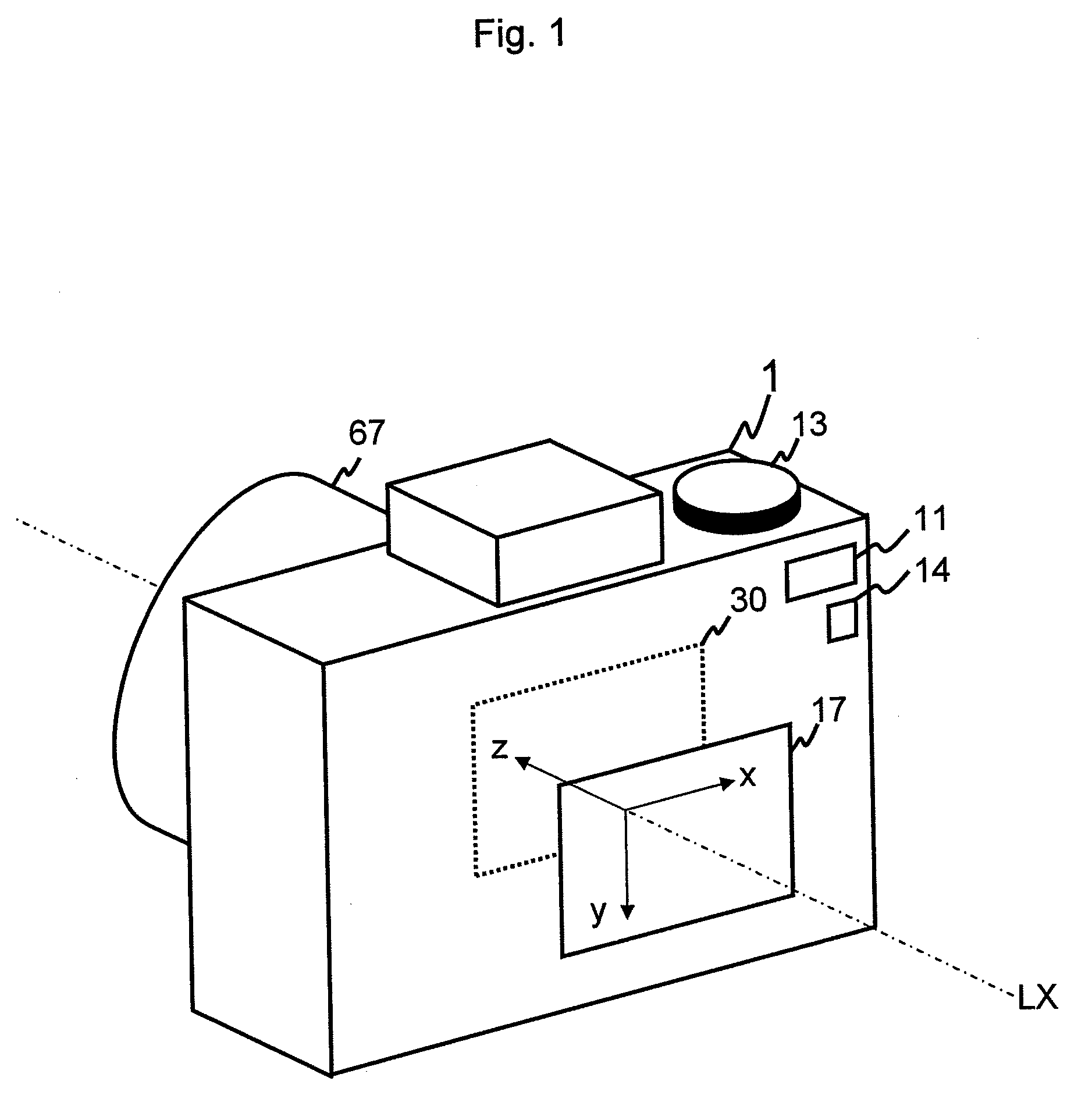
[0032]The present invention is described below with reference to the embodiment shown in the drawings. In the embodiment, the photographic apparatus 1 is a digital camera. A camera lens (i.e. taking lens) 67 of the photographic apparatus 1 has the optical axis LX.

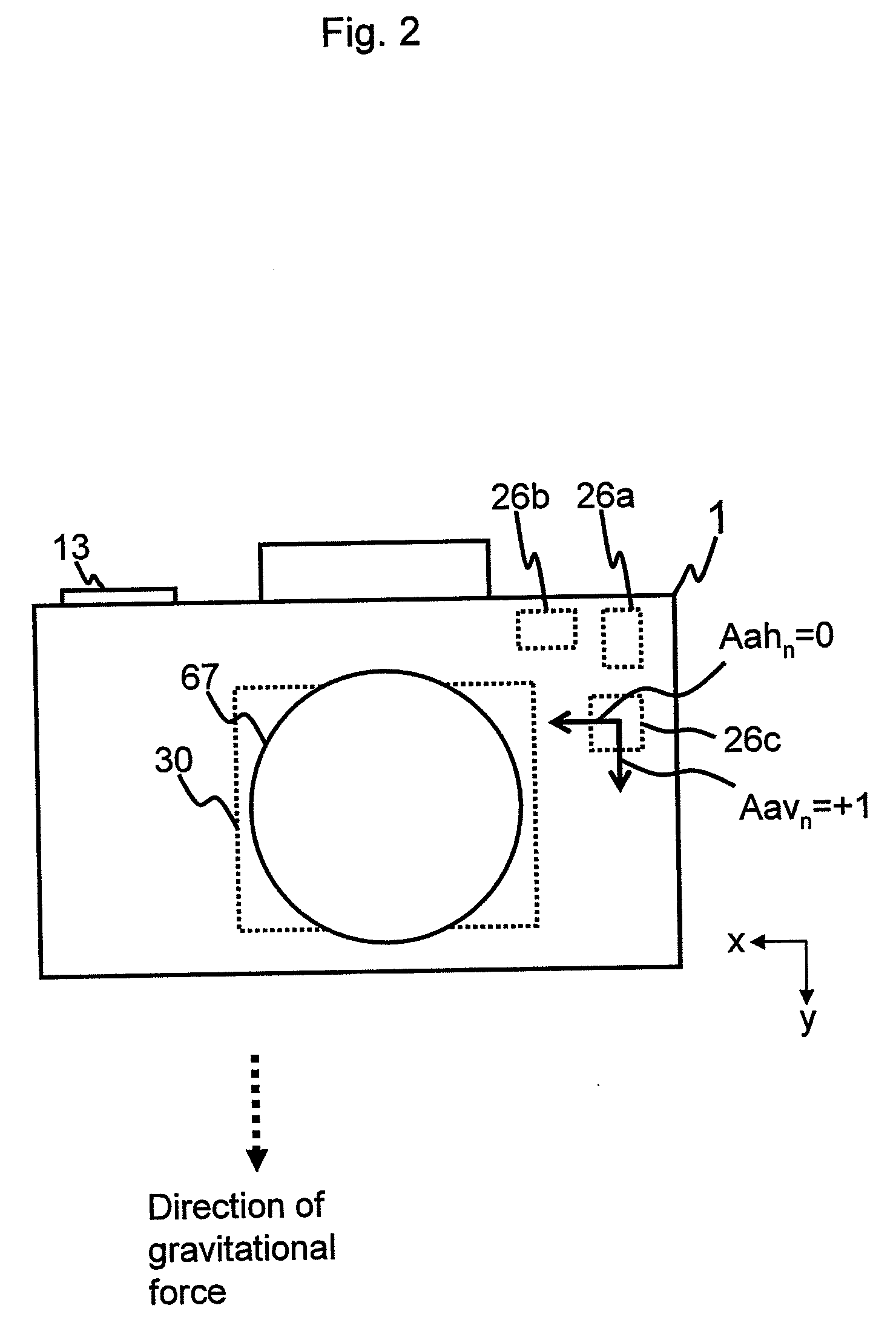
[0033]By way of orientation in the embodiment, the x direction, the y direction, and the z direction are defined (see FIG. 1). The x direction is the direction perpendicular to the optical axis LX. The y direction is the direction perpendicular to the optical axis LX and the x direction. The z direction is the direction parallel to the optical axis LX and perpendicular to both the x direction and the y direction.

[0034]The relationships between the direction of gravitational force and the x direction, the y direction, and the z direction, change according to the orientation of the photographic apparatus 1.

[0035]For example, when the photographic apparatus 1 is held in the first horizontal orientation, in other words, when th...


PUM


Abstract

A photographic apparatus comprises a movable platform and a controller. The movable platform has an imager, and is movable and rotatable in an xy plane. The controller performs a movement control of the movable platform for an inclination correction based on an inclination angle of the photographic apparatus formed by rotation of the photographic apparatus around the optical axis, as measured with respect to a level plane, for a first stabilization for correcting hand shake caused by yaw, and for a second stabilization for correcting hand shake caused by pitch. The controller performs a determination of whether the inclination correction is to be performed, on the basis of a first hand-shake quantity caused by yaw for the first stabilization, a second hand-shake quantity caused by pitch for the second stabilization, and the inclination angle.

Description

BACKGROUND OF THE INVENTION[0001]1. Field of the Invention[0002]The present invention relates to a photographic apparatus, and in particular, to a photographic apparatus that performs a rotational movement such as an inclination correction or the like.[0003]2. Description of the Related Art[0004]There is known a type of image stabilization (also known as anti-shake, but hereinafter, simply “stabilization”) apparatus for a photographic apparatus. The image stabilization apparatus corrects for the effects of hand shake by moving a movable platform including an image stabilization lens or by moving an imager (an imaging sensor) in an xy plane perpendicular to an optical axis of a taking lens of the photographic apparatus, in accordance with the amount of hand shake that occurs during the imaging process.[0005]Japanese unexamined patent publication (KOKAI) No. 2006-71743 discloses an image stabilization apparatus that calculates hand-shake quantity on the basis of hand shake due to yaw,...

Claims


Application Information

Patent Timeline
IPC IPC(8): G03B17/00G03B5/00H04N5/232
CPCG03B17/00H04N5/23287H04N5/23258H04N23/6812H04N23/687
Inventor UENAKA, YUKIO
Owner PENTAX RICOH IMAGING CO LTD
Learn More