Vascular anchoring system and method

a technology of vascular anchoring and vascular valve, applied in the field of implanted systems, can solve the problems of further increase of challenges, misalignment or undesired consequences,

Active Publication Date: 2009-09-17
PACESETTER INC
View PDF2 Cites 72 Cited by
  • Summary
  • Abstract
  • Description
  • Claims
  • Application Information

AI Technical Summary

Problems solved by technology

For an implant system sized for insertion within a vascular area there are challenges in positioning and maintaining the implant in a desired location within the vascular area.
These challenges can be further increased wh

Method used


Image

  • Vascular anchoring system and method
  • Vascular anchoring system and method
  • Vascular anchoring system and method

Examples


Embodiment Construction

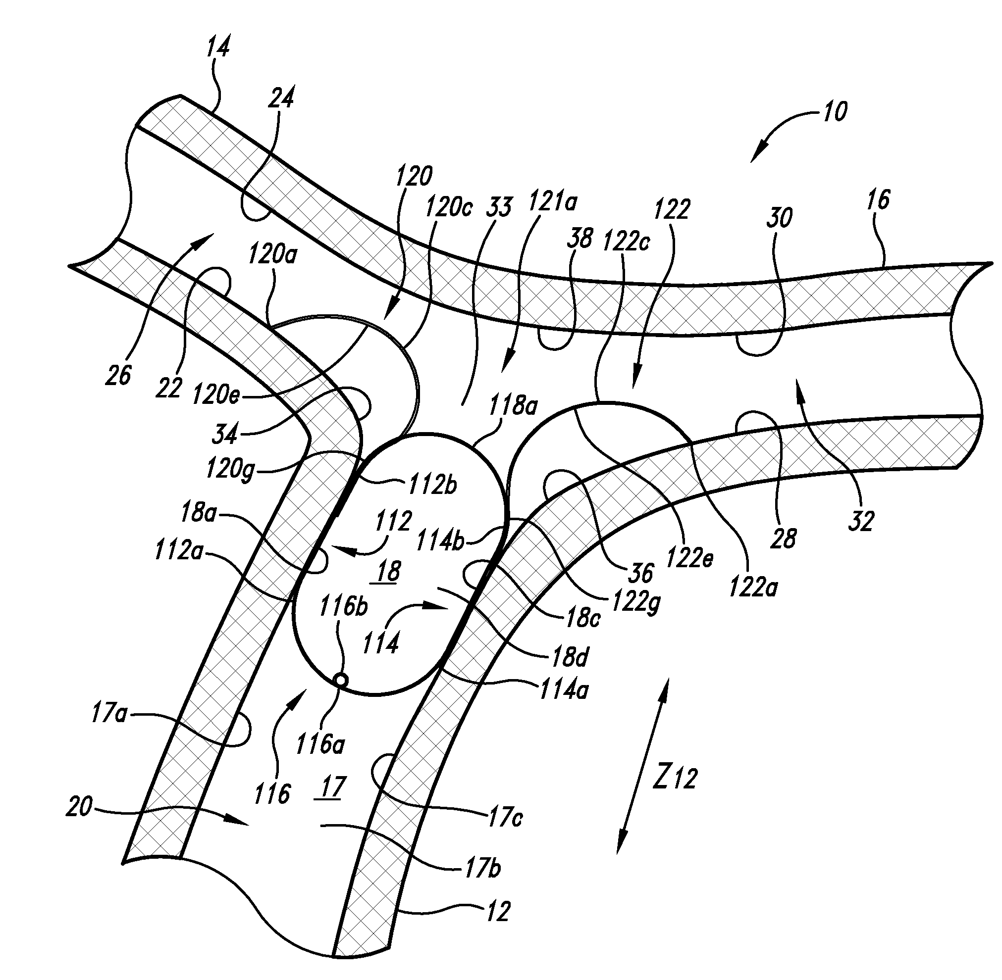
[0055]As described herein vascular anchoring systems are used to position an implant in a vascular area such as a bifurcated vasculature with relatively high fluid flow, for instance, in an area of a pulmonary artery with associated left and right pulmonary arteries.

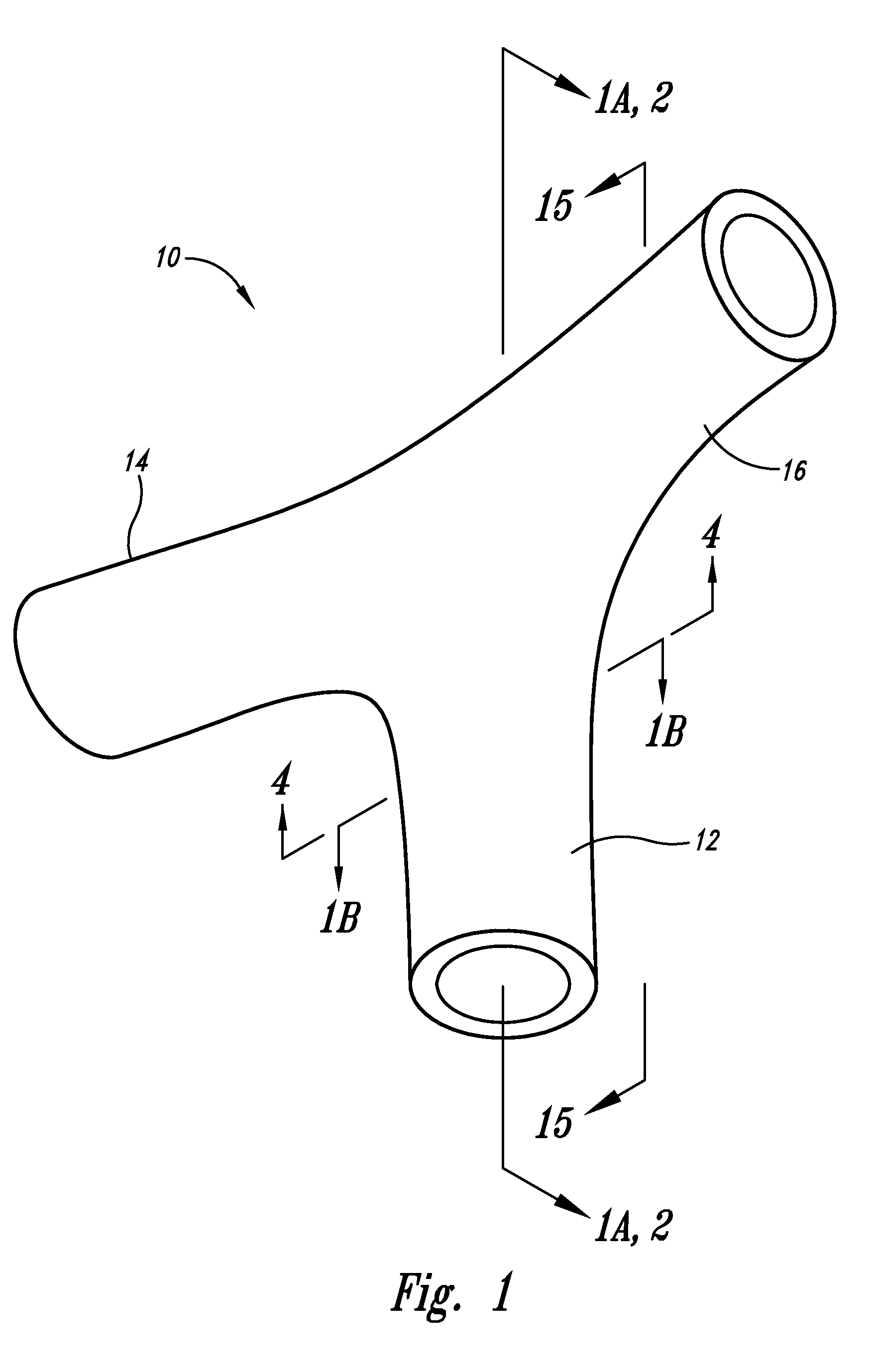
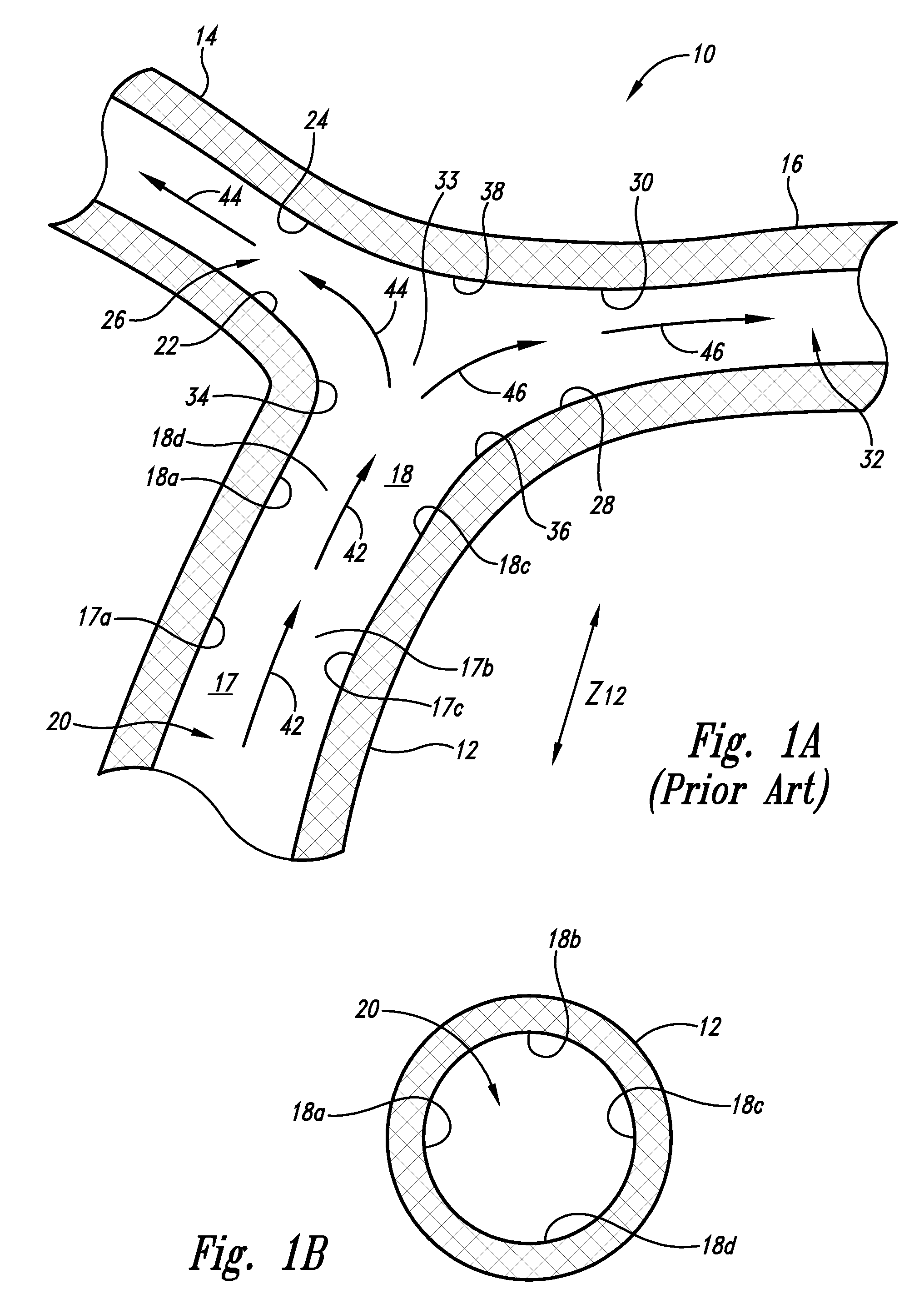
[0056]As shown in FIG. 1 an exemplary vascular area is depicted as a bifurcated vasculature 10 to receive versions of the vascular anchoring system disclosed herein. The bifurcated vasculature 10 is shown in FIG. 1A has having a vascular trunk 12 that extends longitudinally approximately along a dimensional axis Z and splits into a first vascular branch 14 and a second vascular branch 16. For illustrative purposes the vascular trunk 12 has been depicted in the Figures including FIGS. 1A and 1B with labels as having four distal surface locations of a distal trunk surface portion 17: a first distal surface location 17a, a second distal surface location 17b, a third distal surface location 17c, and a fourth distal surface l...


PUM


Abstract

As described herein vascular anchoring systems are used to position an implant in a vascular area such as a bifurcated vasculature with relatively high fluid flow, for instance, in an area of a pulmonary artery with associated left and right pulmonary arteries. Implementations include an anchoring trunk member having a first anchoring trunk section and a second anchoring trunk section. Further implementations include a first anchoring branch member extending from the anchoring trunk member. Still further implementations include a second anchoring branch member extending from the anchoring trunk member.

Description

BACKGROUND OF THE INVENTION[0001]1. Field of the Invention[0002]The present invention is directed generally to implant systems.[0003]2. Description of the Related Art[0004]For an implant system sized for insertion within a vascular area there are challenges in positioning and maintaining the implant in a desired location within the vascular area. These challenges can be further increased when the implant is sectioned into portions that need to be positioned relative to one another. Unintended movement of such portions, such as near or inside a heart organ, can lead to misalignment or undesired consequences.BRIEF DESCRIPTION OF THE SEVERAL VIEWS OF THE DRAWING(S)[0005]FIG. 1 is a perspective-fragmented view of an exemplary vascular area depicted as a bifurcated vasculature to receive a vascular anchoring system disclosed herein.[0006]FIG. 1A is a sectional fragmented view of the bifurcated vasculature of FIG. 1 taken along the 1A-1A line with fluid flow proceeding from a vascular tru...

Claims


Application Information

Patent Timeline
IPC IPC(8): A61F2/06A61F2/82A61F2/86
CPCA61F2/848A61F2/86A61F2/954A61F2230/0008A61F2002/821A61F2002/9665A61F2220/0008A61F2/966
Inventor JOHNSON, TIMOTHYKEILMAN, GEORGE W.
Owner PACESETTER INC
Why Eureka
Try Eureka