Printing Control System, Printing Request Terminal, Printer, and Printing Control Method

a printing control system and printing control technology, applied in the field of printing control systems, can solve the problems of corporate color printing not being in the desired color, limited printing expression,

Inactive Publication Date: 2009-08-27
SEIKO EPSON CORP
View PDF5 Cites 5 Cited by
  • Summary
  • Abstract
  • Description
  • Claims
  • Application Information

AI Technical Summary

Benefits of technology

[0018]According to this configuration, the ink is mixed with each other on a printing sheet and the spreading e

Problems solved by technology

However, in the technique of JP-A-10-309834, since the specific color ink can be assigned but the time interval for ejecting ink cannot be specified, there is a problem that the expression of prints is limited.
For example, when a corporate color of a company is printed by combination of primary color ink, the corporate color is varied every printing and thus the corporate color cannot be printed in a desired color.

Method used


Image

  • Printing Control System, Printing Request Terminal, Printer, and Printing Control Method
  • Printing Control System, Printing Request Terminal, Printer, and Printing Control Method
  • Printing Control System, Printing Request Terminal, Printer, and Printing Control Method

Examples


first embodiment

[0052]A first embodiment of the invention is now described in detail with reference to the accompanying drawings.

A. Configuration of Printing System

[0053]A configuration of a printing system to which the invention is applied is now described.

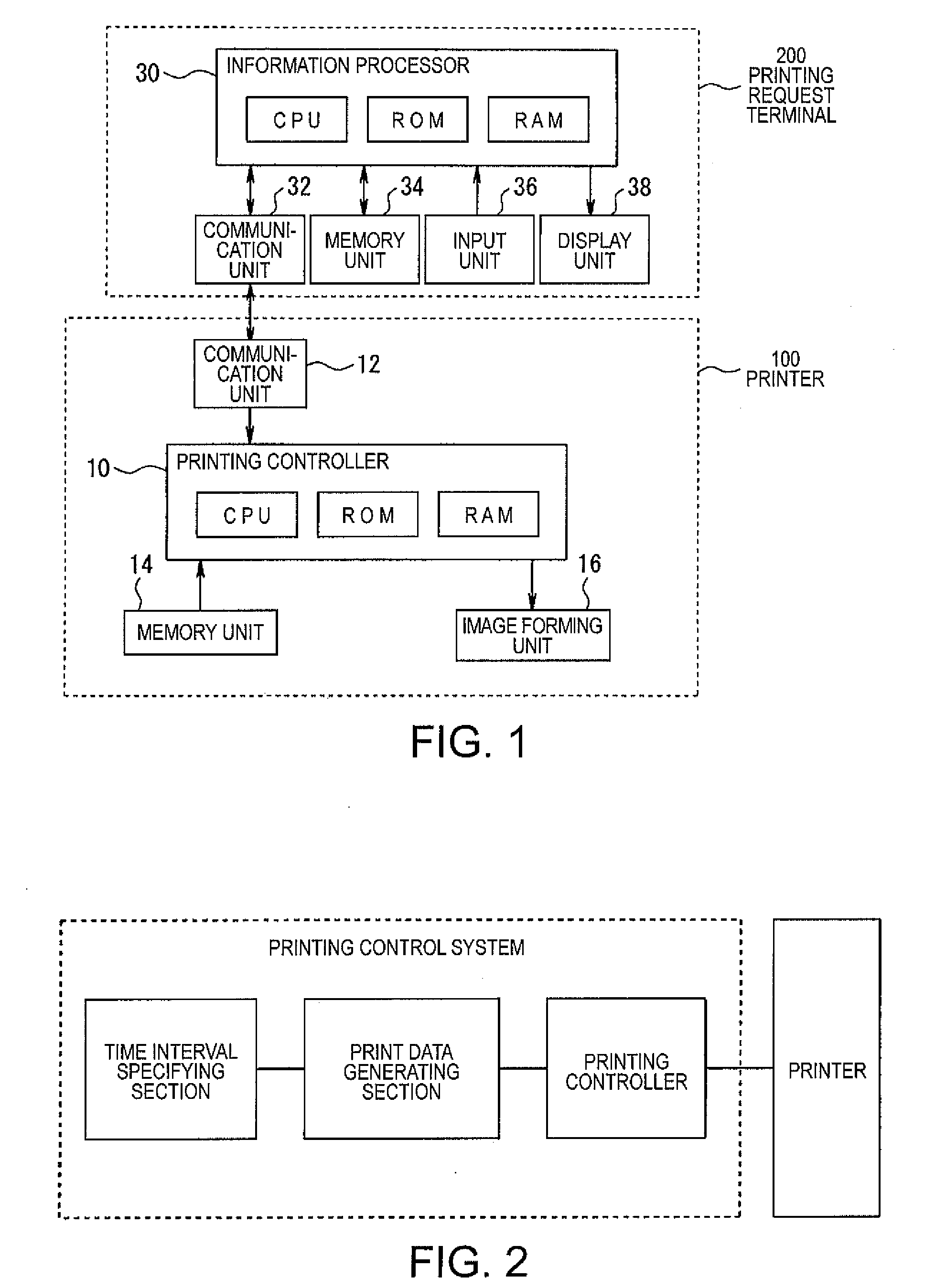
[0054]FIG. 1 is a block diagram illustrating a hardware configuration of a printing system. In FIG. 1, a printer 100 and a printing request terminal 200 requesting the printer 100 for performing a printing operation are connected to each other through a communication cable so as to communicate with each other. Here, both a serial printer and a line printer can be applied as the printer 100, but the serial printer applied as the printer will be described below.

[0055]The printer 100 includes a printing controller 10 controlling a printing operation, a communication unit 12 transmitting and receiving data to and from a printing request terminal 200, a memory unit 14 including a hard disk (HD) that can store data or tables as files, and an image for...

second embodiment

[0151]A second embodiment of the invention is now described.

[0152]FIG. 13 is a diagram illustrating a case where the circle is first drawn and then the rectangle is drawn thereon in T seconds thereafter. In this embodiment, as shown in FIG. 13, the circle is drawn with color B and then the rectangle is overwritten and drawn thereon with color A in T seconds thereafter.

[0153]When the drawing data shown in FIG. 5 is prepared in the printing request terminal 200, the bit map data is generated every drawing layer, the bit map data is stored in the bit map storage area and the necessary drawing parameters are stored in the drawing parameter storage area.

[0154]FIGS. 14A, 14B, and 14C are diagrams illustrating data structures of the bit map storage area and the drawing parameter storage area.

[0155]Color information “B” for the respective pixels of the circle is stored in the bit map storage area of drawing layer 1 as shown in FIG. 14A and color information “A” of the respective pixels of t...


PUM


Abstract

A printing control system controlling a printer performing a printing operation by ejecting a plurality of ink including specific color ink or special ink. A time interval specifying section specifies a time interval for ejecting the ink when the plurality of ink including the specific color ink or the special ink is ejected to perform the printing operation. A print data generating section generates print data for controlling the ejection of the ink every rank, which is determined as an ejection time of the ink as viewed in time series, on the basis of the time interval specified by the time interval specifying section. A printing control section allows the plurality of ink to be ejected in the time interval specified by the time interval specifying section by sequentially controlling the printer on the basis of the print data sequentially acquired from a first rank among the print data of all ranks generated by the print data generating section.

Description

CROSS-REFERENCE TO RELATED APPLICATIONS[0001]This application claims the benefit of priority under 35 USC 119 of Japanese application no. 2008-043935, filed on Feb. 26, 2008, and Japanese application no. 2008-271736, filed on Oct. 22, 2008, which are incorporated herein by reference.BACKGROUND[0002]1. Technical Field[0003]The present invention relates to a system and method of controlling a printer performing a printing operation by ejecting plural ink, and more particularly, to a printing control system, a printing request terminal, a printer, and a printing control method, which are suitable for diverse expression of prints.[0004]2. Related Art[0005]A technique is known of assigning specific color ink to colors of pixels specified in an operating system (OS) when plural ink including specific color ink is ejected to perform a printing operation (JP-A-10-309834).[0006]However, in the technique of JP-A-10-309834, since the specific color ink can be assigned but the time interval for...

Claims


Application Information

Patent Timeline
IPC IPC(8): B41J29/38
CPCB41J2/21G06K2215/0082G06K15/102
Inventor MURAI, KIYOAKI
Owner SEIKO EPSON CORP
Why Eureka
Try Eureka