Tidal Flow Power Generation

a technology of tidal flow and power generation, which is applied in the direction of tidal stream/damless hydropower, water power plants, marine vessel transportation, etc., can solve the problems of difficulty in deployment of such systems on the seabed in limited time, and the failure to achieve successful utilisation of tidal flow power generation solutions

Inactive Publication Date: 2009-06-25
TIDAL ENERGY
View PDF14 Cites 26 Cited by
  • Summary
  • Abstract
  • Description
  • Claims
  • Application Information

AI Technical Summary

Problems solved by technology

One of the major obstructions to successful utilisation of tidal flow power generation solutions is the difficulty of deployment of such systems on the seabed in the limited time between periods of high tidal current ...

Method used


Image

  • Tidal Flow Power Generation
  • Tidal Flow Power Generation
  • Tidal Flow Power Generation

Examples


Embodiment Construction

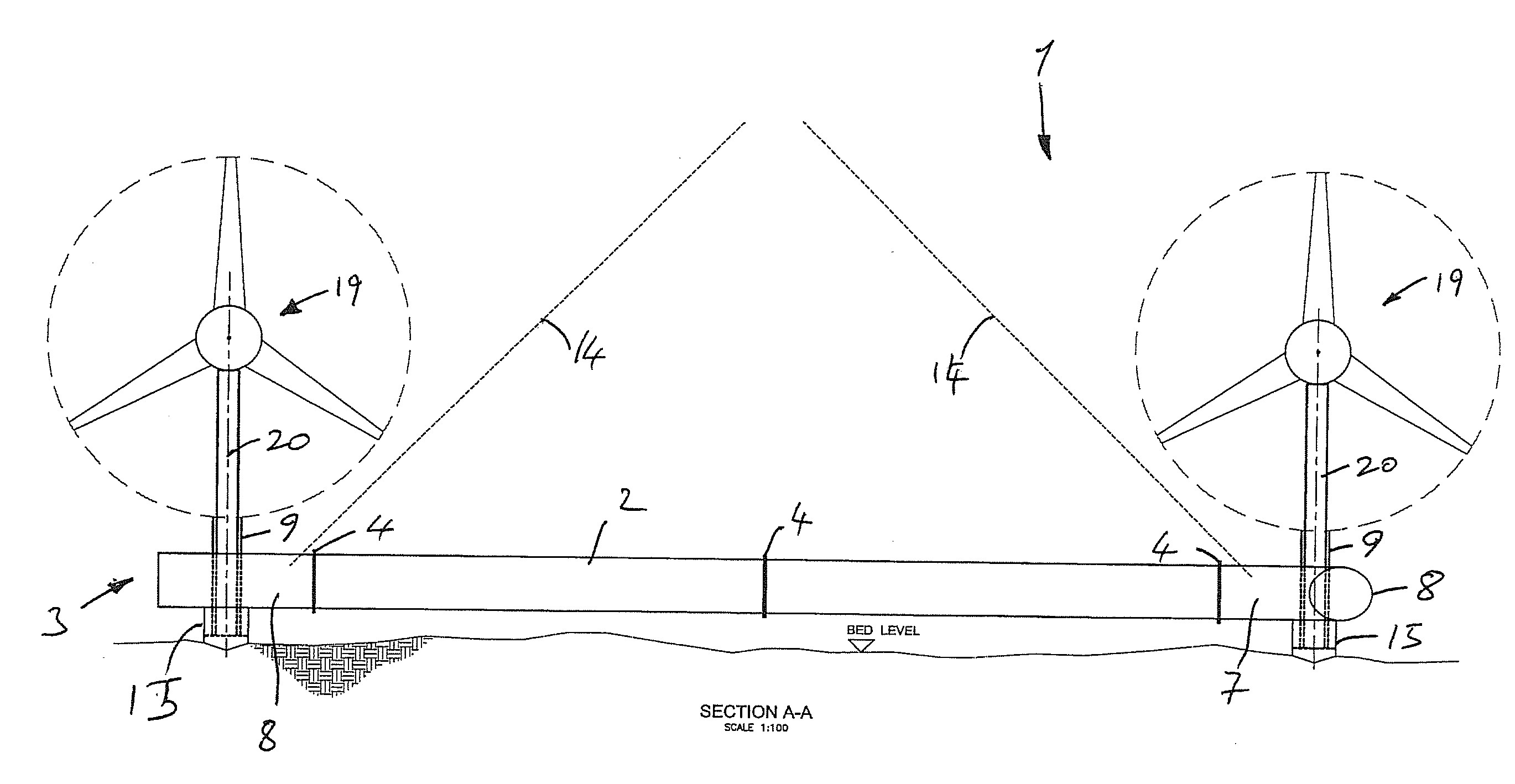
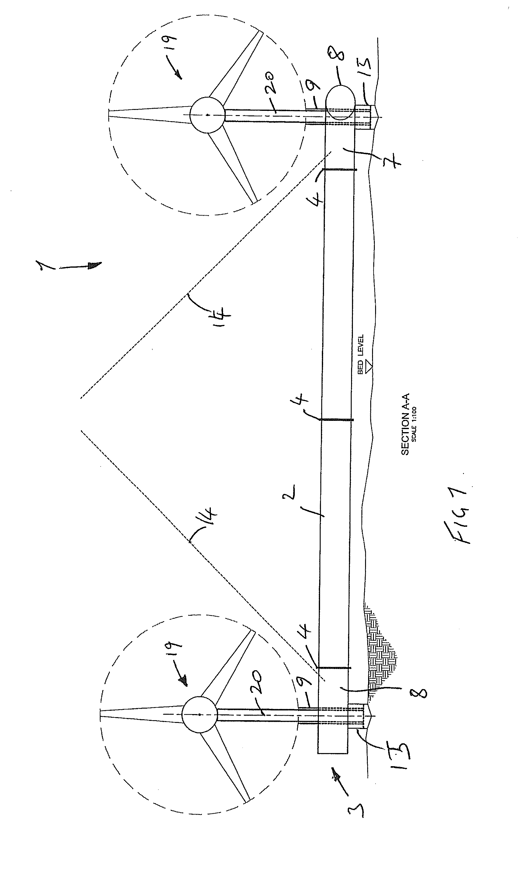
[0027]Referring to the drawings, there is shown a tidal flow energy generation arrangement 1. The tidal flow energy generation arrangement 1 is required to be deployed in extreme conditions. To be commercially competitive with other forms of power production areas of the seabed of high tidal flow energy concentration need to be utilised. These areas are difficult and dangerous to work in and the structure and its installation and retrieval need to take into account significant environmental hazards. The current flow, for example, is fast, typically upward of 4 Knots, and may be faster than a floating crane or anchors can hold. Areas are often in deep water, which may be deeper than those in which a piling rig can operate. Storm conditions can cause costly delays and postponement. Tidal reversal is twice a day and the time between tidal reversal may be very short (for example between 45 and 90 minutes). Additionally, in such high tidal flow areas, the seabed is scoured of sediment an...


PUM


Abstract

A structure for a tidal flow energy generation system is fabricated from tubular framework having tubular modules with mounts for respective tidal flow turbine nacelles. The node modules include tubular limbs extending in transverse directions and elongate tubes and provided to interconnect with the tube limbs of the node modules. The structure can be pre-fabricated and transported to a location for deployment. The structure can be deployed by means of hovering the assembled structure to the seabed, for example by means of flooding the structure.

Description

FIELD OF THE INVENTION[0001]The present invention relates to tidal flow power generation.BACKGROUND TO THE INVENTION[0002]Various schemes have been proposed and utilised for tidal flow power generation. One of the major obstructions to successful utilisation of tidal flow power generation solutions is the difficulty of deployment of such systems on the seabed in the limited time between periods of high tidal current flow rates. Also there are technical problems in ensuring that the system is sufficiently securely anchored in place on the seabed, but quickly deployable and capable of being raised clear of the sea surface for maintenance.DEFINITION OF THE INVENTION[0003]According to a first aspect the present invention provides a structure for use in a tidal flow energy generation system, the structure comprising a tubular framework comprising:[0004]a plurality of tubular node modules having mounting means for mounting a respective tidal flow turbine nacelle, the respective node modul...

Claims


Application Information

Patent Timeline
IPC IPC(8): E02B9/08
CPCE02B9/08F03B13/264F03B17/061F05B2230/50F05B2240/40F05B2240/91F03B13/12F05B2240/95F05B2240/97F05B2250/11F05B2250/313Y02E10/28F05B2240/914Y02P70/50Y02E10/30Y02E10/20
Inventor AYRE, RICHARD
Owner TIDAL ENERGY
Why Eureka
Try Eureka