
Control panel assembly for laundry device

a technology for controlling panels and laundry devices, applied in emergency actuators, textiles and paper, other washing machines, etc., can solve the problems of inconvenient modern living, achieve convenient button manipulation, improve the button configuration of the laundry device, and be easily recognized

Inactive Publication Date: 2009-06-04
LG ELECTRONICS INC
View PDF4 Cites 16 Cited by
  • Summary
  • Abstract
  • Description
  • Claims
  • Application Information

AI Technical Summary

Benefits of technology

[0016]An object of the present invention is to provide a control panel assembly of a laundry device, by which a manipulation of buttons is facilitated by improving button configurations of the laundry device.
[0018]To achieve these and other advantages and in accordance with the purpose of the present invention, as embodied and broadly described, a control panel assembly of a laundry device according to the present invention includes a control panel provided to a front side of a body and a keypad provided to the control panel, the keypad having a plurality of button groups enabling a washing to be performed by selecting a plurality of operational conditions once.
[0025]More preferably, the board guide includes a tact switch provided to a position opposing the corresponding button to come into contact with the corresponding button and an LED lamp provided next to the corresponding tact switch to emit light by an activation of the corresponding tact switch. And, the control panel assembly further includes a lamp supporter provided between the keypad and the board guide, wherein an LED guide perforated by the corresponding LED lamp is provided to a surface of the lamp supporter to prevent a diffusion of the light of the LED lamp and wherein a pressurizing part is provided to the lamp supporter to transfer an elastic force of the corresponding button to the corresponding tact switch.
[0028]More preferably, each of a plurality of the display units includes a transparent window enabling light to be externally transmitted and a plurality of the display units are built in one body of a plurality of the buttons by double injection molding. And, the control panel assembly further includes a plurality of lamp guides projected from backsides of a plurality of the buttons to prevent the lights of a plurality of the LED lamps from diffusing, respectively.

Problems solved by technology

Yet, in case of the rainy season or irregular weather, the natural drying of the laundry is delayed to cause inconvenience for modern living.

Method used


Image

  • Control panel assembly for laundry device
  • Control panel assembly for laundry device
  • Control panel assembly for laundry device

Examples


first embodiment

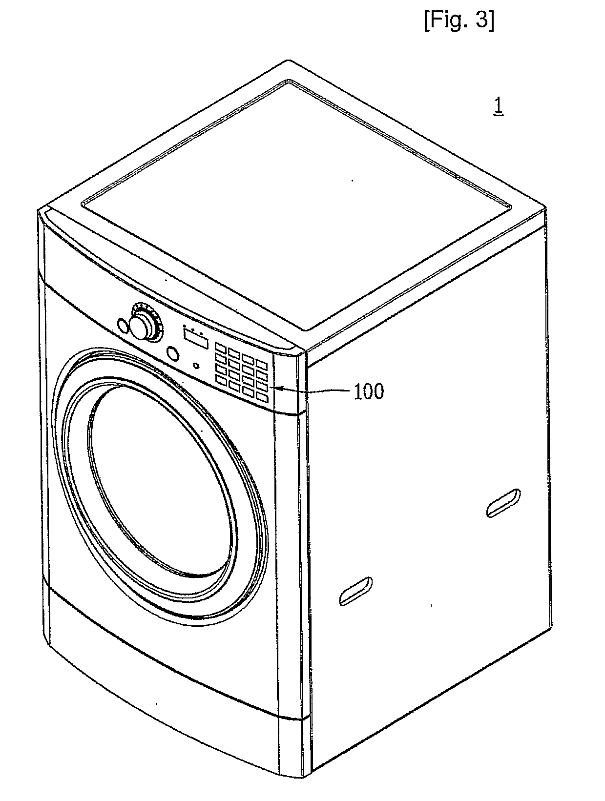
[0056]A control panel assembly of a laundry device (hereinafter named ‘dryer’) according to the present invention is explained with reference to FIGS. 3 to 8 as follows.

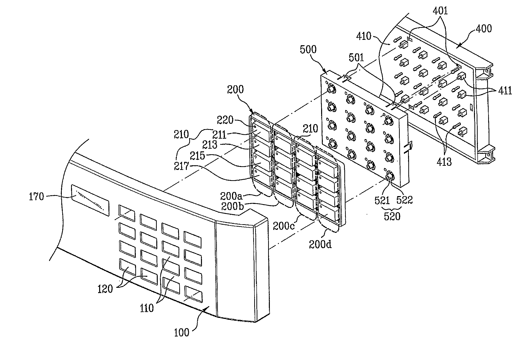
[0057]FIG. 3 is a perspective diagram of a dryer according to an embodiment of the present invention, FIG. 4 is a front diagram of a control panel according to an embodiment of the present invention, in which an installed configuration of a button group is schematically shown, FIG. 5 is an exploded perspective diagram of a control panel assembly according to an embodiment of the present invention, FIG. 6 is a perspective diagram of a keypad according to an embodiment of the present invention, in which a backside of the keypad is shown, FIG. 7 is an exploded perspective diagram of a control panel assembly according to an embodiment of the present invention, in which a backside of the control panel assembly is shown, and FIG. 8 is an exploded perspective diagram of a control panel assembly according to an embodiment of...

second embodiment

[0087]A control panel assembly of a laundry device (hereinafter ‘dryer’) according to the present invention is explained with reference to FIG. 3, FIG. 4, and FIGS. 8 to 11 as follows.

[0088]Referring to FIG. 3, FIG. 4 and FIG. 8, a control panel assembly of a laundry device according to a second embodiment of the present invention includes a control panel 100 provided to a front side of a body 1 and a keypad 200 provided to a front side of the control panel 100.

[0089]The keypad 400, as shown in FIG. 4, is configured to have a plurality of button groups 200a, 200b, 200c and 200d to enable a washing to be performed by selecting a plurality of operational conditions once.

[0090]Each of a plurality of the button groups 200a, 200b, 200c and 200d is provided to enable one of functions including a dryness, a drying temperature, a drying time and an additional function to be executed by a single action.

[0091]In this case, each of a plurality of the button groups 200a, 200b, 200c and 200d can...

third embodiment

[0119]A control panel assembly of a laundry device (hereinafter ‘dryer’) according to the present invention is explained with reference to FIG. 3, FIG. 4, and FIGS. 12 to 15 as follows.

[0120]Referring to FIG. 3, FIG. 4 and FIG. 2, a control panel assembly of a laundry device according to a third embodiment of the present invention includes a control panel 100 provided to a front side of a body 1, a keypad 200 provided to a front side of the control panel 100, a board guide 400 provided in rear of the keypad 200, and a lamp supporter 500 provided between the keypad 200 and the board guide 400.

[0121]The keypad 400, as shown in FIG. 4, is configured to have a plurality of button groups 200a, 200b, 200c and 200d to enable a washing to be performed by selecting a plurality of operational conditions once.

[0122]Each of a plurality of the button groups 200a, 200b, 200c and 200d is provided to enable one of functions including a dryness, a drying temperature, a drying time and an additional ...


PUM


Abstract

A control panel assembly of a laundry device is disclosed, by which a manipulation of buttons (200) is facilitated by improving button configurations of the laundry device. The present invention includes a control panel (100) provided to a front side of a body and a keypad provided to the control panel, the keypad (200) having a plurality of button groups (200a, 200b, 200c, 200d) enabling a washing to be performed by selecting a plurality of operational conditions once.

Description

TECHNICAL FIELD[0001]The present invention relates to a control panel assembly of a laundry device, and more particularly, to a button assembly. Although the present invention is suitable for a wide scope of applications, it is particularly suitable for facilitating to manufacture and manipulate the assembly.BACKGROUND ART[0002]Generally, a laundry device is the general term for a washing machine for washing and dewatering cycles, a dryer for a drying cycle, and a dryer washer for washing and drying cycles.[0003]The dryer is configured to evaporate water from an object to be dried in a manner of heating air using a heating means and then blowing the heated air into a drum.[0004]Normally, a laundry is transferred to a laundry-drying frame for a natural drying. Yet, in case of the rainy season or irregular weather, the natural drying of the laundry is delayed to cause inconvenience for modern living.[0005]So, the demand for a device capable of a natural drying of laundry regardless of...

Claims


Application Information

Patent Timeline
IPC IPC(8): H01H13/76D06F34/28
CPCD06F39/005H01H13/70H01H2219/014H01H2219/064H01H2233/002H01H2221/07H01H2223/054H01H2229/046H01H2231/012H01H2221/024D06F2101/14D06F34/28D06F2105/58D06F2101/18D06F2101/16D06F2103/00
Inventor YOON, JU HANHWANG, SUNG GI
Owner LG ELECTRONICS INC
Learn More