
After transmission return signal

a transmission unit and signal technology, applied in the field of data networks, can solve the problem of adding a significant amount of storage to the transmission unit, and achieve the effect of improving the efficiency of transmission units

Active Publication Date: 2009-04-30
SIGMA DESIGNS ISRAEL S D I
View PDF8 Cites 11 Cited by
  • Summary
  • Abstract
  • Description
  • Claims
  • Application Information

AI Technical Summary

Problems solved by technology

However, they add a significant amount of storage to the transmission units, especially since the transmission and after transmission queues are typically per flow (i.e. per source / destination pair).

Method used


Image

  • After transmission return signal
  • After transmission return signal
  • After transmission return signal

Examples


Embodiment Construction

[0029]In the following detailed description, numerous specific details are set forth in order to provide a thorough understanding of the invention. However, it will be understood by those skilled in the art that the present invention may be practiced without these specific details. In other instances, well-known methods, procedures, and components have not been described in detail so as not to obscure the present invention.

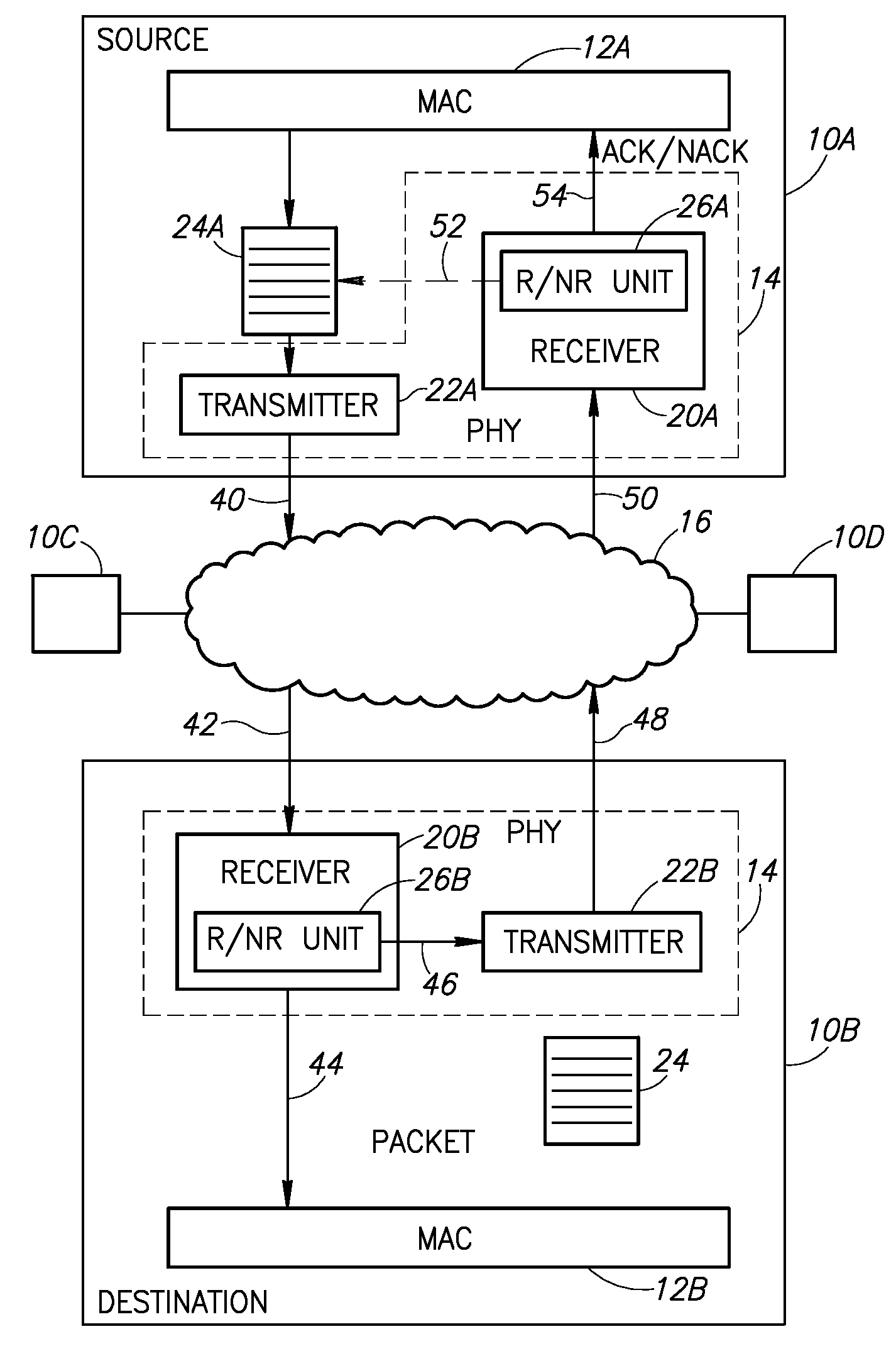
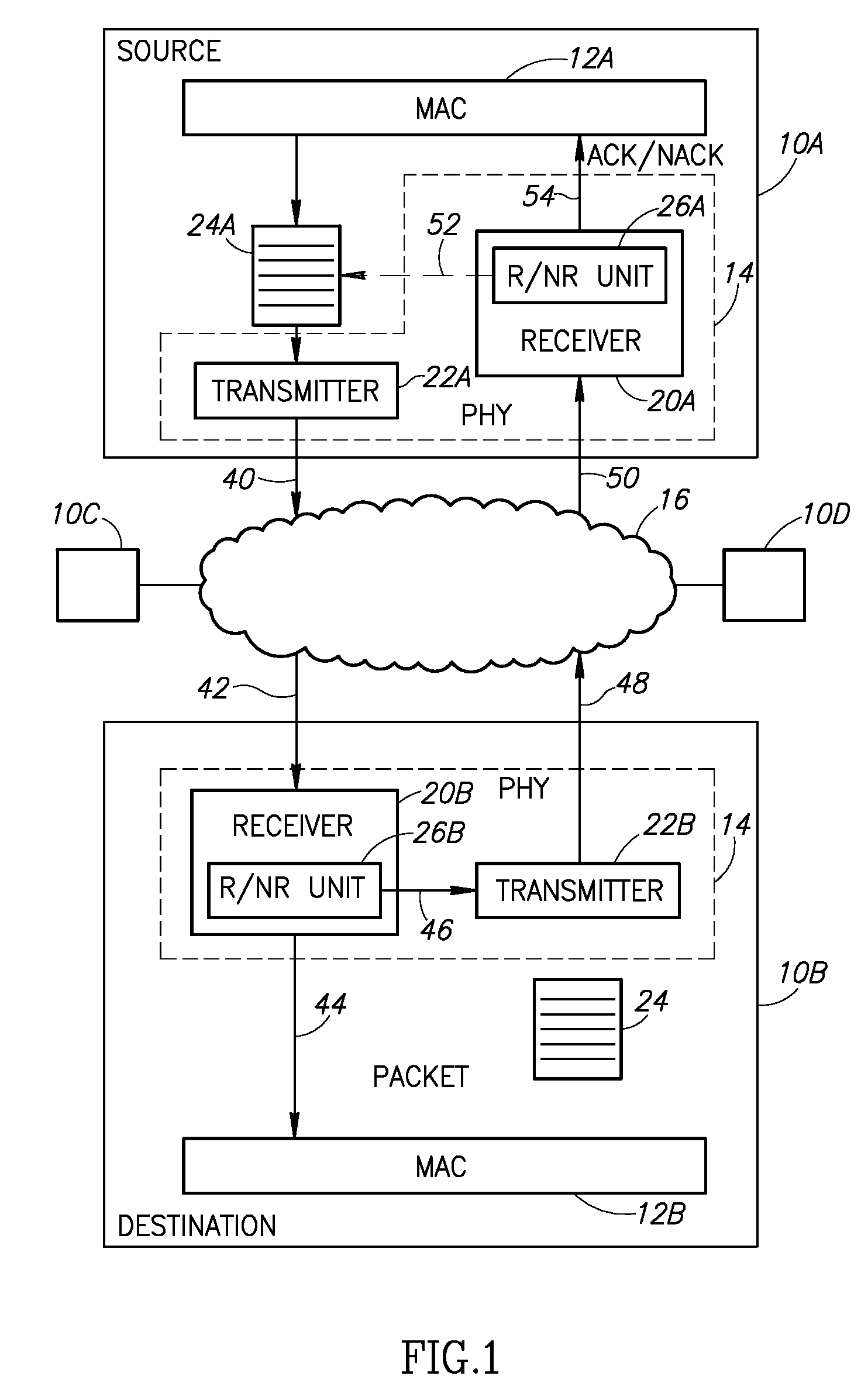
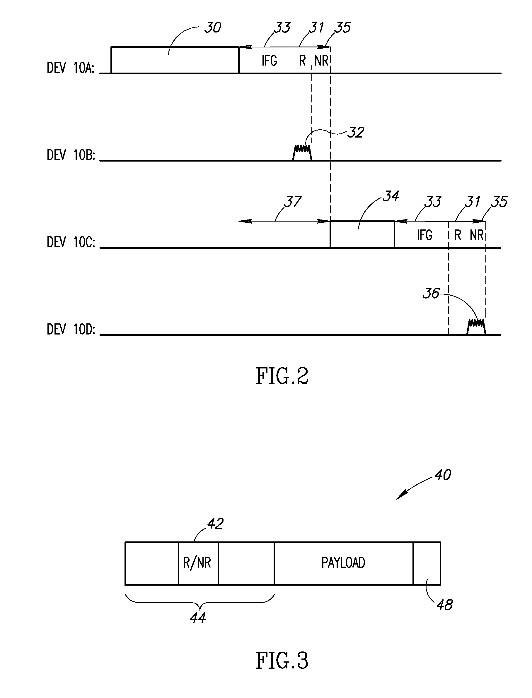
[0030]Applicants have realized that the determination that a packet has been successfully received occurs during receipt and thus, is available very shortly after the transmission finishes. In accordance with a preferred embodiment of the present invention, the time between transmissions (which previously was just an inter-frame gap (IFG)) is increased slightly, becoming an inter-frame period, to allow a short “return” signal to be transmitted on the network. In accordance with a preferred embodiment of the present invention, the return signal generally is simpler...


PUM


Abstract

A method includes transmitting a next transmission after an inter-frame period after a previous transmission, wherein the inter-frame period is long enough to allow a return signal responding to the previous transmission. A network device includes a receiver to receive a transmission from a source device and a transmitter at least to transmit a return signal to the source device indicating successful receipt or lack thereof of the transmission during a return period forming part of an inter-frame period after the transmission.

Description

CROSS-REFERENCE TO RELATED APPLICATIONS[0001]This application claims benefit from U.S. Provisional Patent Applications No. 60 / 983,615, filed Oct. 30, 2007 and 60 / 989,658, filed Nov. 21, 2007, which are hereby incorporated in their entirety by reference.FIELD OF THE INVENTION[0002]The present invention relates to data networks in general and to transmission receipt in such networks in particular.BACKGROUND OF THE INVENTION[0003]Data networks are ubiquitous. They are utilized to transfer information from one location to the next and they do so through network protocols. One common protocol is the TCP / IP protocol, which adds headers and footers carrying transmission information to packets of “payload” data. When a packet is transmitted, it is saved for a period of time, in case the packet was not properly received and needs to be retransmitted. There may be a transmission queue, with the packets waiting for transmission, and a separate “after transmission” queue, holding already transm...

Claims


Application Information

Patent Timeline
Patent Type & Authority Applications(United States)
IPC IPC(8): H04L12/56
CPCH04L1/1874H04L1/188H04L12/40H04L2001/0093H04L47/10
Inventor ROZEN, ILANKERN, RANFRANCO, REUVENLURIE, AHARONA
Owner SIGMA DESIGNS ISRAEL S D I
Learn More