Stripper rubber with integral retracting retention member connection apparatus

a technology of stripper rubber and retention member, which is applied in the direction of mechanical equipment, sealing/packing, and well accessories, etc., can solve the problems of increased risks for rig personnel from accidental scalding, burns or contamination, and serious injury to rig workers, so as to facilitate the connection of stripper rubber, facilitate the transmission of rotary torque loads, and facilitate the effect of connection

Inactive Publication Date: 2009-04-23
HAMPTON IP HLDG
View PDF9 Cites 4 Cited by
  • Summary
  • Abstract
  • Description
  • Claims
  • Application Information

AI Technical Summary

Benefits of technology

[0014]In view of the foregoing, the present invention, through one or more of its various aspects, embodiments and / or specific features or sub-components, is thus intended to bring out one or more of the advantages that will be evident from the disclosures made herein. More specifically, the present invention facilitates connection of a stripper rubber to drilling head equipment. Embodiments of the present invention provide a fast, simple and reliable means for detachably attaching the stripper rubber to drilling head equipment and, optionally, facilitating transmission of rotary torque loads applied on the stripper rubber from the rotating drill string and exerted from the stripper rubber onto a corresponding rotating component of the drilling head equipment (e.g., an inner barrel of the rotating control head).

Problems solved by technology

As modern wells are drilled ever deeper, or into certain geological formations, very high temperatures and pressures may be encountered at the drilling head.
These rigorous drilling conditions pose increased risks to rig personnel from accidental scalding, burns or contamination by steam, hot water and hot, caustic well fluids.
There is a danger of serious injury to rig workers when heavy tools are used to make a stripper rubber connection at the drilling head.
The practice of using heavy tools to tighten a bolt, for example, can result in over-tightening, to the point where the threads or the bolt head become stripped.
Both results are undesirable.
Even worse, vibration and other drilling stresses can cause bolts or screws to work themselves loose and fall out.
If one or more falls downhole, the result can be catastrophic.
The drill bit can be ruined.
If the well bore has been cased, the casing may be damaged and have to be repaired.
In some circumstances, stripped or over tightened bolts or screws make it very difficult if not impossible to disengage the stripper rubber from the drilling head assembly to perform recommended maintenance or parts replacement.

Method used


Image

  • Stripper rubber with integral retracting retention member connection apparatus
  • Stripper rubber with integral retracting retention member connection apparatus
  • Stripper rubber with integral retracting retention member connection apparatus

Examples


Embodiment Construction

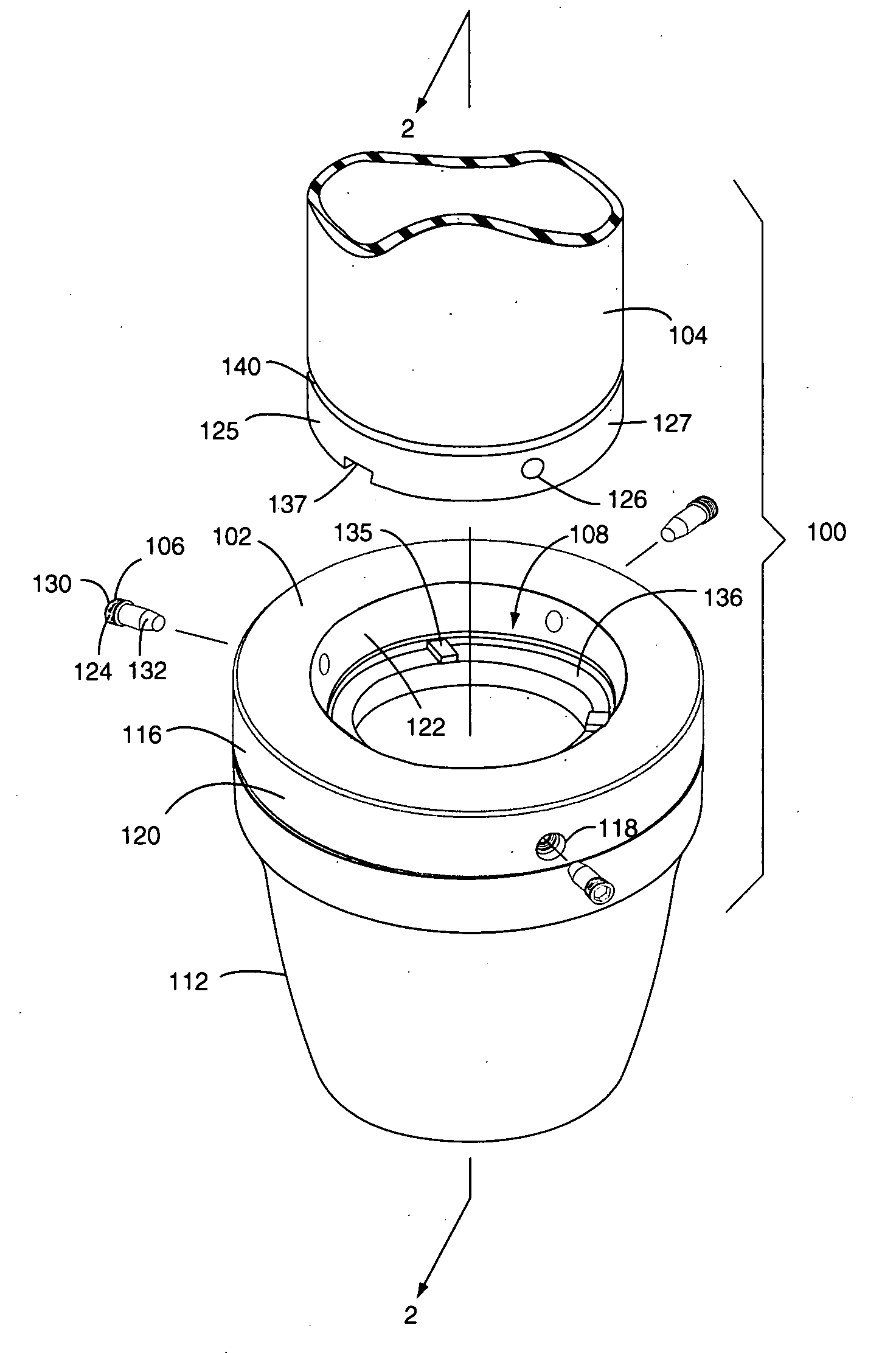
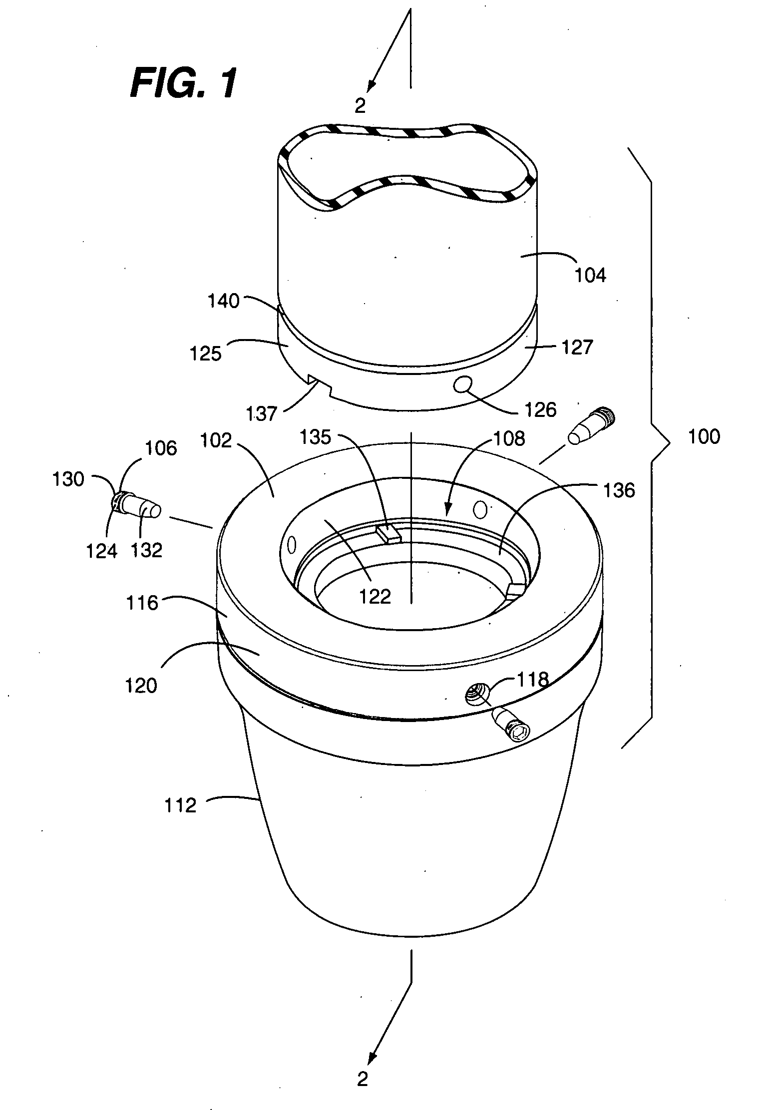
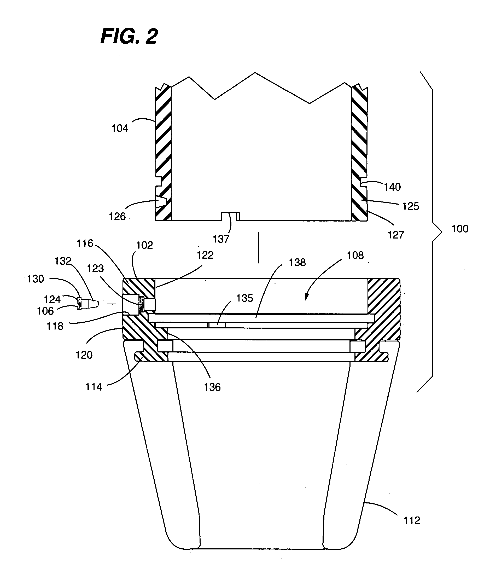
[0023]Referring to FIGS. 1-3, an embodiment of a system 100 for disconnectably connecting a stripper rubber to drilling head equipment in accordance with the present invention is shown. The system 100 includes a stripper rubber insert 102, a bearing assembly inner barrel 104 and a plurality of retention members 106. As is discussed below in greater detail, the stripper rubber insert 102, the bearing assembly inner barrel 104 and the retention members 106 are jointly configured for being interconnected in a manner that is advantageous, novel and non-obvious. Aspects of the present invention that contribute to such advantageous, novel and non-obvious interconnection include, but are not limited to, such interconnection providing a fast, simple and reliable means for detachably attaching the stripper rubber insert 102 to the bearing assembly inner barrel 104 in a manner that facilitates transmission of rotary torque loads applied on the stripper rubber 102 from a rotating drill string ...


PUM


Abstract

A stripper rubber insert comprises a central bore and a plurality of retention member bores substantially perpendicular to the central bore. The retention member bores are angularly spaced apart around a perimeter of the stripper rubber insert. Each one of the retention member bores extends through an exterior insert edge face and an interior insert edge face. Each one of the retention member bores includes a respective retention member securing structure therein.

Description

FIELD OF THE DISCLOSURE[0001]The present disclosure relates to connectors and connector systems for making mechanical connections. More particularly, the disclosure provides apparatus, systems and methods for facilitating a stripper rubber being connected to and disconnected from equipment, such as for example a bearing assembly, of a drilling head to pressure-seal the interior of a well bore for the circulation, containment or diversion of drilling materials through the well during drilling operations.BACKGROUND[0002]Oil, gas, water and geothermal wells are typically drilled with a drill bit connected to a hollow drill string which is inserted into a well casing cemented in the well bore. A drilling head is attached to the well casing, wellhead or to associated blowout preventer equipment, for the purposes of sealing the interior of the well bore from the surface and facilitating forced circulation of drilling fluid through the well while drilling or diverting drilling fluids away ...

Claims


Application Information

Patent Timeline
Patent Type & Authority Applications(United States)
IPC IPC(8): E21B19/00
CPCE21B33/085
Inventor WILLIAMS, JOHN R.
Owner HAMPTON IP HLDG
Why Eureka
Try Eureka