
Method for detection of the presence of a load and drive circuit

a technology of load and drive circuit, applied in the direction of reference comparison, pulse technique, instruments, etc., can solve problems such as failure of inductive load

Active Publication Date: 2009-03-19
INFINEON TECH AG
View PDF8 Cites 17 Cited by
  • Summary
  • Abstract
  • Description
  • Claims
  • Application Information

AI Technical Summary

Problems solved by technology

For example, an interruption in an electrical line connection between the load and the drive circuit or within the inductive load itself can lead to a failure of the inductive load.

Method used


Image

  • Method for detection of the presence of a load and drive circuit
  • Method for detection of the presence of a load and drive circuit
  • Method for detection of the presence of a load and drive circuit

Examples


Embodiment Construction

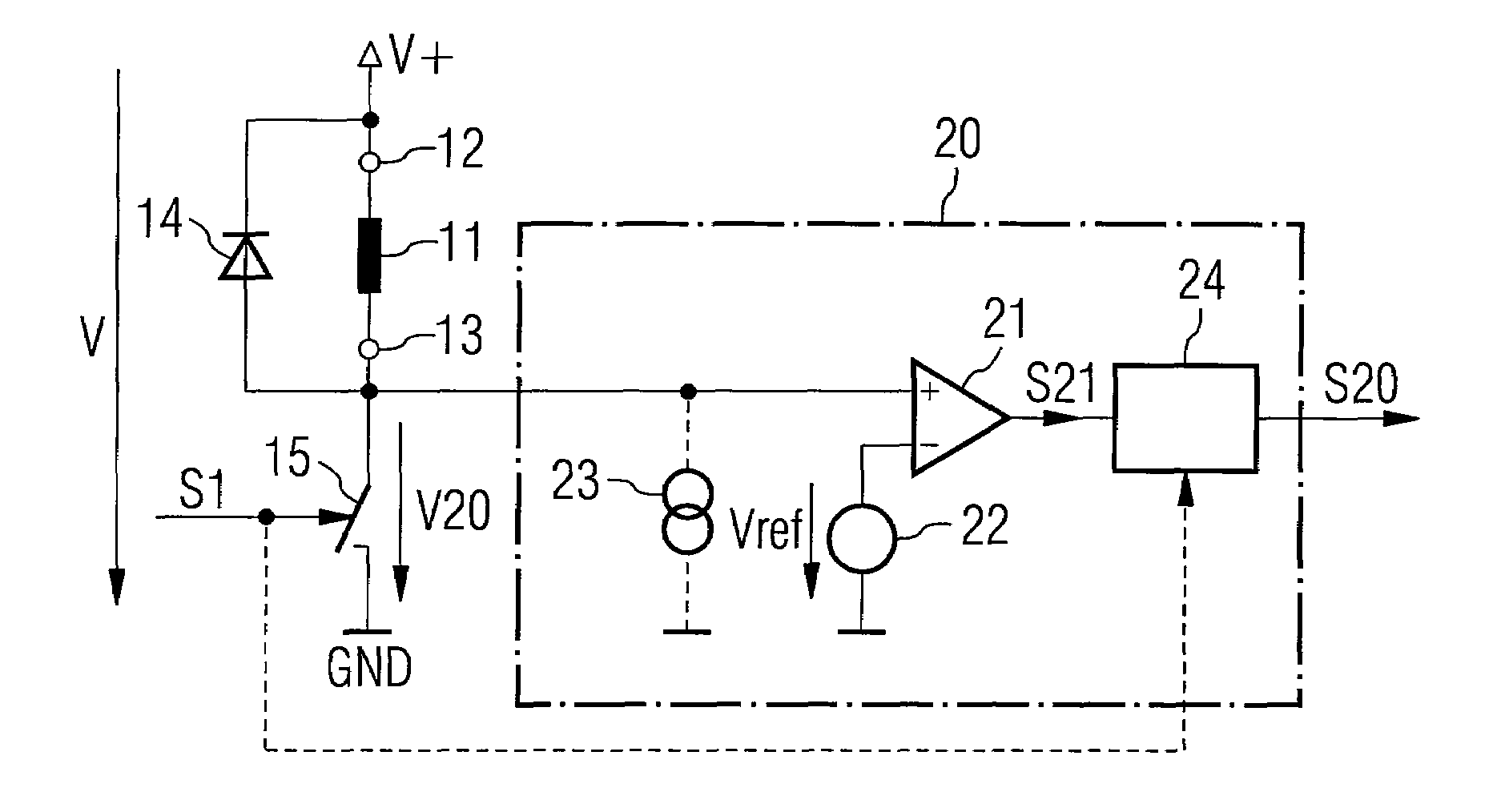
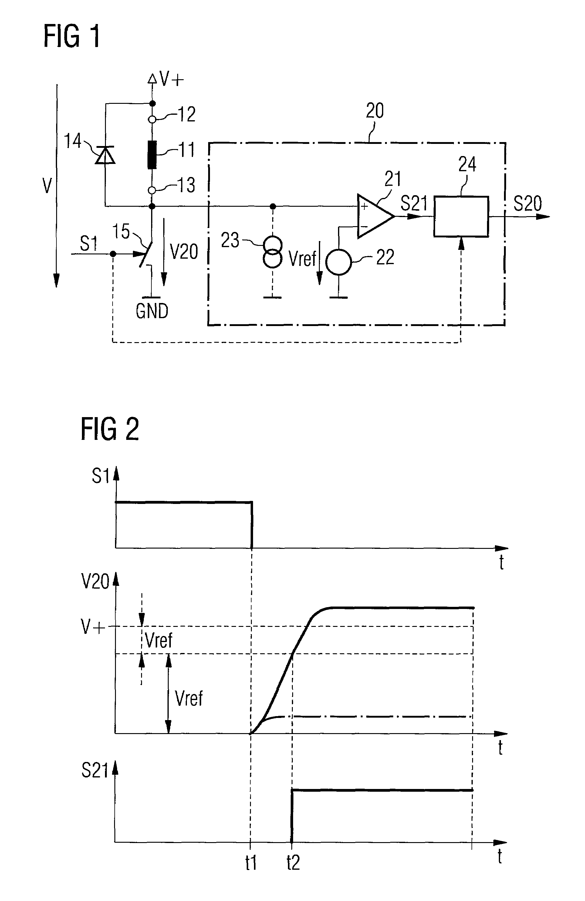
[0018]FIG. 1 shows a first exemplary embodiment of a drive circuit for driving a load 11, in particular an inductive load. By way of example, this inductive load 11 is a direct-current electric motor or a solenoid valve, and can be driven by cyclic application of a supply voltage. In the course of a cyclic drive process such as this, a drive voltage is applied to the inductive load during each of successive drive periods for a switched-on period which is followed by a switched-off period. The duty ratio (duty cycle) of the cyclic drive, that is to say the ratio between the switched-on period and the total duration of the drive period, governs the motor current and thus the torque, for example in the case of an electric motor. Indirectly, this also influences the rotation speed.

[0019]For cyclic application of a supply voltage between the connecting terminals 12, 13 and thus across the load 11—if there is one—the drive circuit which is illustrated in FIG. 1 has a voltage supply termin...


PUM


Abstract

Methods and apparatuses for detection of a presence of a load. A method may include, for example, applying and subsequently removing a supply voltage across the pair of nodes, comparing an electrical potential at one of the pair of nodes at a time after the supply voltage is removed with a reference value, and generating a signal having a value that depends upon an outcome of the comparison.

Description

TECHNICAL BACKGROUND[0001]Inductive loads, such as electric motors or solenoid valves, are used for widely differing purposes, for example in motor vehicles. Particularly in the case of applications which are safety-relevant, such as occupant protection systems, or which influence the emission of hazardous substances from the vehicle, there are stringent requirements for the reliability of the inductive loads and for the drive circuits which drive the loads. For example, an interruption in an electrical line connection between the load and the drive circuit or within the inductive load itself can lead to a failure of the inductive load. The presence of the load and its correct operation are in this case intended to be detected regularly, ideally during operation.SUMMARY[0002]Various aspects are described herein. For example, according to some aspects, methods and apparatuses are provided for detection of a presence of a load. A method may include, for example, applying and subsequen...

Claims


Application Information

Patent Timeline
Patent Type & Authority Applications(United States)
IPC IPC(8): G01R17/00
CPCG01R31/006G01R31/024G01R31/026H03K17/08122H03K17/08128H03K17/687H03K17/0828H03K17/18H03K17/567H03K17/64H03K17/662H03K17/0822G01R31/54
Inventor KALTENEGGER, MARTINSCHWARZENBERGER, GUNTERTREBO, HEINRICHLANG, PETER
Owner INFINEON TECH AG
Learn More