
Oil well polish rod clamp for use with a rotator on a beam pumping unit

a technology for polishing rods and beam pumps, which is applied in the direction of drilling casings, wells, drilling pipes, etc., can solve the problems of reducing the service life of the beam pumping unit, affecting the service life of the pumping unit, so as to increase the longitudinal or axial gripping capacity, reduce the contact area, and increase the gripping pressure

Inactive Publication Date: 2009-03-12
ROBBINS & MYERS ENERGY SYST
View PDF31 Cites 11 Cited by
  • Summary
  • Abstract
  • Description
  • Claims
  • Application Information

AI Technical Summary

Benefits of technology

[0011]An oil well polish rod clamp includes a unitary metallic cylindrical housing and a plurality of axially spaced set screws for pressing the rod into secure engagement with the housing. A textured inner surface of the housing increases the longitudinal or axial gripping capacity on the rod, which may be rotated inside an oil well by a rod rotator and reciprocated by a beam pumping unit to actuate a downhole pump. The housing may include a plurality of axially short cylindrical portions with annular gaps between upper and lower portions to increase gripping pressure by reducing the contact area with the rod. A plurality of bolts or other force applying member may be used to force the rod into gripping engagement with the housing.

Problems solved by technology

The depth of these “coal-bed methane” gas wells is typically less than 1,500 feet, making a standard size beam pumping unit economically wasteful in terms of physical size, capital expense, and horsepower.
Due to variations in well depth and the fact that polish rods are commonly manufactured in lengths from 11 feet to 22 feet, this clamp must be capable of gripping anywhere along the length of the polish rod, as it is impractical to simply screw a nut on the upper threaded end of the polish rod for a positive load bearing connection between the polish rod and carrier bar.
A nut may have to be spaced several feet above the carrier bar, which is extremely impractical.
This will eventually cause perforation of the tubing and also more commonly a separation of the sucker rod string hundreds of feet downhole.
Both are expensive failures to correct.
However, this clamp was discontinued many years ago because the rod gripping member utilized slip-like members with sharp teeth that created noticeable indentions and stress risers in the highly stressed polish rod.
When used with a rod rotator, the rotary motion combined with the indentations and stress risers resulted in unacceptable breakage and separation of the polish rod due to fatigue.
The added body material on the opposing sides makes this design unsuitable since the clamp cannot be rotated between the 4 inch wire rope spacing on bridles found on small beam pumping units.
Users of small beam pumping units that wish to prolong the life of the sucker rod string and tubing have had no practical way to utilize a rod rotator, since commercially available but grossly asymmetrical polish rod clamps cannot rotate between the 4 inch space between the wire ropes comprising the bridle assembly.
Heretofore, these clamps accordingly could only be used on such small pumping units without a rod rotator.
As a consequence, excessive wear and early failure of the sucker rod string and tubing, and the resulting expensive and frequent maintenance, was accepted as the norm.

Method used


Image

  • Oil well polish rod clamp for use with a rotator on a beam pumping unit
  • Oil well polish rod clamp for use with a rotator on a beam pumping unit
  • Oil well polish rod clamp for use with a rotator on a beam pumping unit

Examples


Embodiment Construction

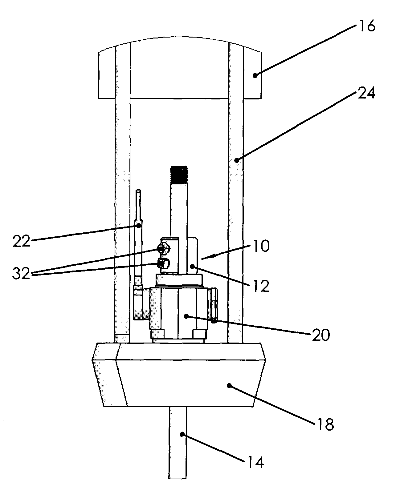
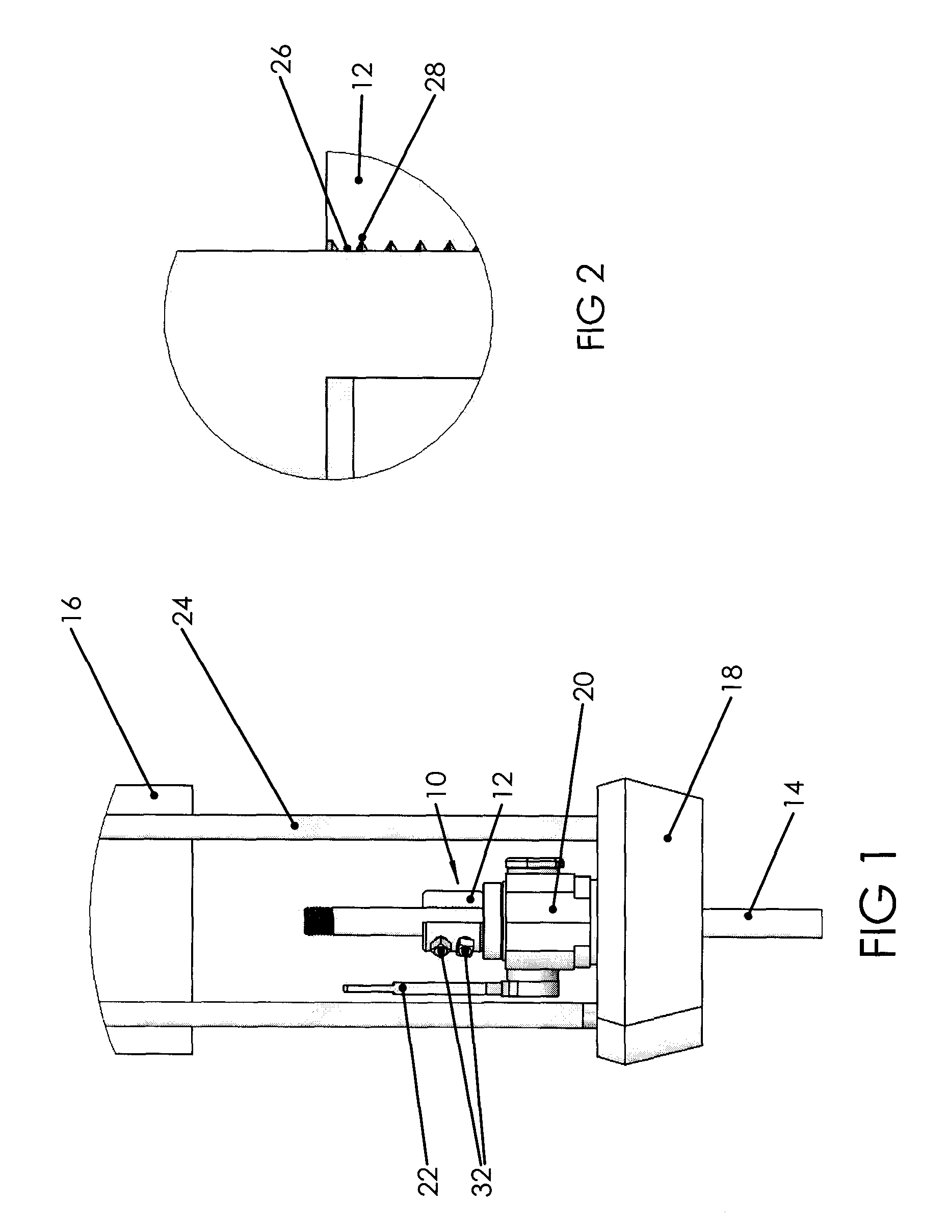
[0017]Referring now to FIG. 1, oil well polish rod clamp 10 of the present invention includes a unitary and generally cylindrical housing 12 with a central bore sized to receive a polish rod 14. FIG. 1 illustrates the lower portion of the horsehead 16 of a beam pumping unit, an accessory carrier bar 18, which is a transverse cross member with a hole sized to allow the polish rod 14 to pass therethrough, and a rod rotator 20 mounted above the carrier bar 18. For the depicted embodiment, the rod rotator has a simple handle 22 for manually rotating the rod. Bridle 24 extends in the conventional manner between the horsehead and the carrier bar, and for small pumping units provides a minimum space between the bridle cables.

[0018]By providing a unitary, monolithic, donut-shaped body, the clamping mechanism associated with a split body and a hinge on one side and bolts or other clamping members on the opposing side are avoided. Also, reliable gripping engagement between the rod and the hou...


PUM


Abstract

An oil well polish rod clamp includes unitary metallic cylindrical housing and a plurality of setscrews. A textured inner surface of the housing increases longitudinal gripping capacity on a rod rotated inside an oil well by a rod rotator and reciprocated by a beam pumping unit to actuate a downhole pump. The inner housing surface may include a plurality of axially short cylindrical portions with annular gaps between upper and lower portions to increase gripping pressure by reducing the contact area with the rod.

Description

RELATED APPLICATIONS[0001]The present invention claims priority from provisional application Ser. No. 60 / 993,450 filed Sep. 12, 2007.FIELD OF THE INVENTION[0002]The present invention relates to oil well polish rod clamps and, more particularly, to an oil well polish rod clamp for use with a rod rotator on a beam pumping unit.BACKGROUND OF THE INVENTION[0003]The smallest oil well beam pumping units commonly used in the oilfield are also used to de-water coal formations to allow the controlled release of methane gas for mine safety, and also for economic benefit as an additional fuel source. The depth of these “coal-bed methane” gas wells is typically less than 1,500 feet, making a standard size beam pumping unit economically wasteful in terms of physical size, capital expense, and horsepower. As a consequence, the popularity of the smallest available beam pumping units has grown substantially in the past 10 years. The beam pumping units that are most ideal for coal-bed methane produc...

Claims


Application Information

Patent Timeline
Patent Type & Authority Applications(United States)
IPC IPC(8): E21B19/02
CPCE21B19/12
Inventor SMITH, LESLIE DEAN
Owner ROBBINS & MYERS ENERGY SYST
Learn More