Movable terminal connecting mechanism

Inactive Publication Date: 2009-02-05
DELTA ELECTRONICS INC
View PDF2 Cites 0 Cited by
  • Summary
  • Abstract
  • Description
  • Claims
  • Application Information

AI Technical Summary

Benefits of technology

[0007]It is an object of the present invention to provide a movable terminal connecting mechanism for implementing the wiring task in a convenient and user-friendly manner.
[0008]Another object of the present invention provides a movable terminal connecting mechanism capable of being stored within the electrical appliance, thereby increasing electrical safety.

Problems solved by technology

Since the terminal block 10 for wiring to the external power cable needs to be configured at the lower portion of the backside of the case 11, the wiring task is troublesome.
Therefore, the wiring task is both labored and time-consuming.

Method used


Image

  • Movable terminal connecting mechanism
  • Movable terminal connecting mechanism
  • Movable terminal connecting mechanism

Examples


Embodiment Construction

[0021]The present invention will now be described more specifically with reference to the following embodiments. It is to be noted that the following descriptions of preferred embodiments of this invention are presented herein for purpose of illustration and description only. It is not intended to be exhaustive or to be limited to the precise form disclosed.

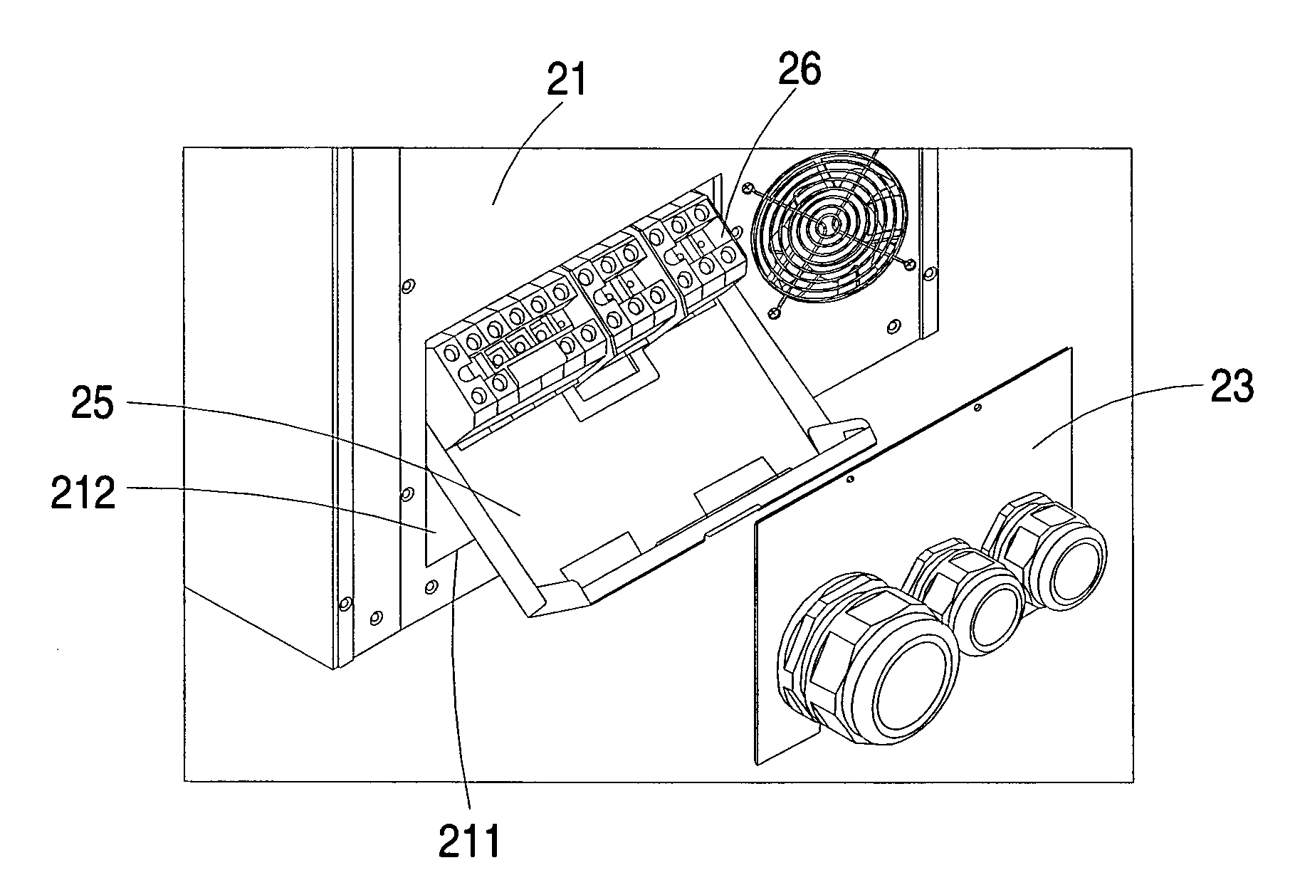
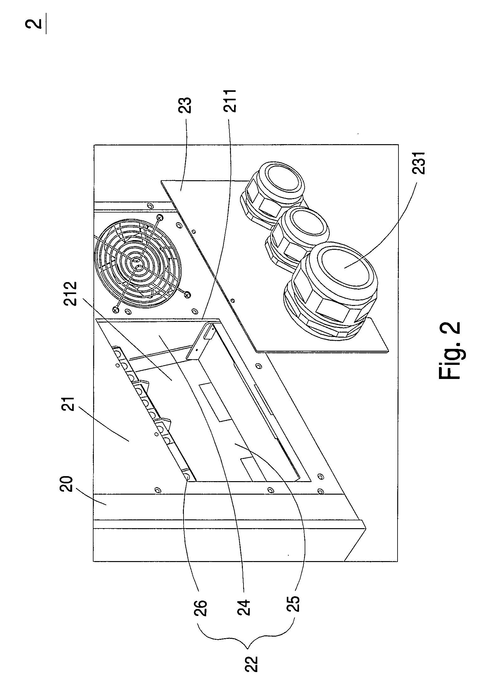
[0022]Please refer to FIG. 2, which is a schematic partial backside view illustrating the lower portion of an electrical appliance according to the present invention. The electrical appliance is for example a power supply apparatus or an uninterruptible power supply (UPS) apparatus. As shown in FIG. 2, the electrical appliance 2 principally includes a case 20. The case 20 includes a frame body 21 and a movable terminal connecting mechanism 22. The frame body 21 includes an entrance 211 and a receptacle 212. The movable terminal connecting mechanism 22 is received in the receptacle 212 of the frame body 21. The movable terminal co...


PUM


Abstract

A movable terminal connecting mechanism of an electrical appliance includes a support part, a carrier part and a first terminal block. The support part is fixed within a frame body of the electrical appliance and includes at least one first retaining structure. The carrier part includes at least one second retaining structure corresponding to the first retaining structure. The carrier part is moved with respect to the support part when the second retaining structure is moved with respect to the first retaining structure. The first terminal block is fixed on the carrier part to be coupled with an external cable. The first terminal block is either partially exposed outside the entrance of the frame body to implement a wiring task of wiring the first terminal block with the external cable, or stored in a receptacle of the frame body.

Description

FIELD OF THE INVENTION[0001]The present invention relates to a terminal connecting mechanism, and more particularly to a movable terminal connecting mechanism.BACKGROUND OF THE INVENTION[0002]Uninterruptible power supply (UPS) apparatuses are widely used to provide stable power to loads. If the voltage of the utility power is subject to a sudden variation or interruption, the power to the loads could be maintained at an applicable level by using the UPS apparatus.[0003]Referring to FIG. 1, a schematic backside view of an uninterruptible power supply (UPS) apparatus is illustrated. The UPS apparatus 1 of FIG. 1 principally includes a case 11 and a plurality of UPS units 12. The backside of each UPS unit 12 has one or more connection ports 13 and several sockets 14. Generally, for operative convenience, the UPS units 12 are distant from the floor. Since the terminal block 10 for wiring to the external power cable needs to be configured at the lower portion of the backside of the case ...

Claims


Application Information

Patent Timeline
IPC IPC(8): H01R13/44
CPCH01R35/00H01R9/223
Inventor CHENG, CHING-WENCHIAO, CHIEN-HUA
Owner DELTA ELECTRONICS INC
Why Eureka
Try Eureka