Hook structure of power tool
- Summary
- Abstract
- Description
- Claims
- Application Information
AI Technical Summary
Benefits of technology
Problems solved by technology
Method used
Image
Examples
first embodiment
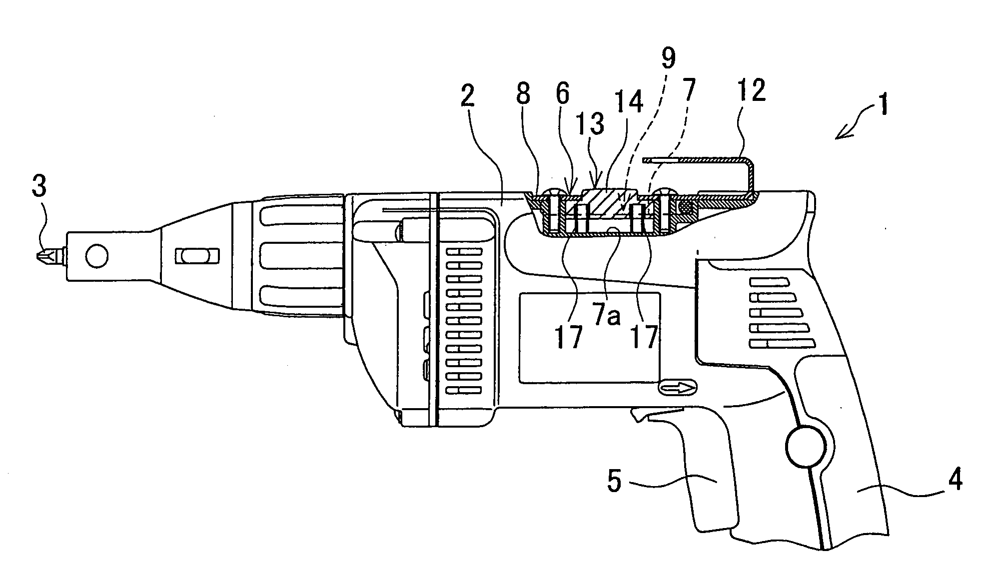
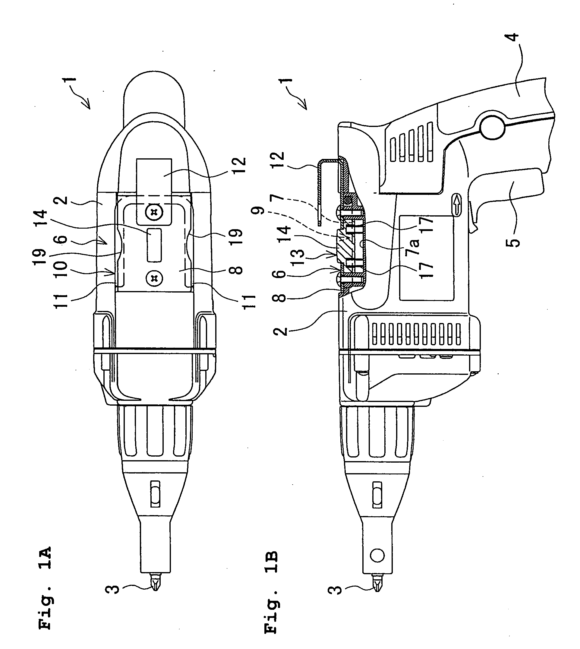
[0031]A power screwdriver 1 shown in FIGS. 1A and 1B is one example of a power tool with a hook structure consistent with the present invention. The power screwdriver 1 is of a type known in the art, and has electric power elements (not shown), such as a motor, a rotation transmission mechanism and a torque limiter, incorporated in a housing 2, to produce and transmit the torque to a screwdriver bit 3 held at a front end (left-hand end in FIGS. 1A and 1B) of the power screwdriver 1. At the rear of the housing 2 of the power screwdriver 1, a grip 4 extending therefrom and having a trigger switch 5 is provided.
[0032]At an upper surface of the housing 2, a hook unit 6 is provided as a hook structure according to a first embodiment of the present invention. The hook unit 6 includes a hook-receiving portion 9 provided in the housing 2 with openings facing leftward and rightward, and a substantially U-shaped hook 10 having two legs 11 which are a left hook leg 11 and a right hook leg 11. ...
second embodiment
[0039]The first embodiment described above exemplifies a hook structure in which one and the same hook can be used at either of the left or right side of the power screwdriver 1, selectively. It is however appreciated that the same hook can also be used at the upper side of the power screwdriver 1 in some modified arrangements. According to a second embodiment of the present invention, one example of such a hook structure is shown as a hook unit 6a in FIG. 4A in which the same elements as in the first embodiment are designated by the same reference numerals, and a duplicate explanation will be omitted in describing the second embodiment.
[0040]This hook unit 6a has no upper hook fixed on the upper plate 8. In the housing 2, a depression 20 is provided at a front side of the recess 7. The depression 20 is recessed in alignment with an imaginary extension line extending frontward from the right groove 11 formed on the right side of the lock button 13 located in the upper-limit position...
third embodiment
[0046]A description will now be given of a third embodiment which offers a selection of angles of upward protrusion of a hook. In a hook unit 6b shown in FIGS. 5A and 5B, a lock button 13 includes an operation part 14 and a locking element 15 provided on the right side of the operation part 14, and a groove 16 formed between the operation part 14 and the locking element 15 is disposed in a center of the hook-receiving portion 9. A depression 20, a coil spring 21 and a lid 22 are disposed in alignment with an imaginary extension line extending frontward from the groove 16 when the lock button 13 is located in the upper-limit position. Moreover, in the hook-receiving portion 9, a constraint block 26 is provided over a left area of a recess 7 to block up the left side of the operation part 14, with a space left at a left side of the constraint block 26, so as to allow the left hook leg 11 to be fitted on the constraint block 26 within the space. The constraint block 26 is also used as ...
PUM
 Abstract
Description
Claims
Application Information
 - R&D
- Intellectual Property
- Life Sciences
- Materials
- Tech Scout
- Unparalleled Data Quality
- Higher Quality Content
- 60% Fewer Hallucinations
Browse by: Latest US Patents, China's latest patents, Technical Efficacy Thesaurus, Application Domain, Technology Topic, Popular Technical Reports.
© 2025 PatSnap. All rights reserved.Legal|Privacy policy|Modern Slavery Act Transparency Statement|Sitemap|About US| Contact US: help@patsnap.com


