
Method and apparatus for three dimensional tomographic image reconstruction of objects

a three-dimensional tomographic image and reconstruction technology, applied in the field of data processing systems, can solve the problems of weather conditions and air quality, and the accuracy of registration becomes extremely difficult, and the limited range of laser imaging detection and range systems

Inactive Publication Date: 2009-01-22
THE BOEING CO
View PDF8 Cites 74 Cited by
  • Summary
  • Abstract
  • Description
  • Claims
  • Application Information

AI Technical Summary

Benefits of technology

This patent describes a system that uses multiple observers (also known as radar sensors) to gather data on a target object or objects. The system includes filters to process the gathered data, a database to store the data, and analysis tools to help make sense of it all. One important feature is a mechanism called a sinogram which helps create a 3-dimensional image of the target object based on the data collected by the observers. Another key component is an optimization algorithm that guides the movements of the observers to improve their effectiveness at collecting relevant data. Overall, this technology allows researchers to better analyze and interpret large amounts of complex data, leading to improved understanding and more accurate detection of targets.

Problems solved by technology

This patent discusses various methods for detecting target objects in 3D spaces through radar and optical techniques such as SAR, stereo synthetic aperture radar, and interferometric system aperture radar. However, these existing technologies have limitations including difficulty with accurately registering points due to clutter and motion, and being dependent upon weather conditions and air quality. There is also a lack of effective detection capabilities at smaller sizes for some applications like airborne surveillance. Thus, there is a technical problem of developing a more robust and versatile detection system capable of overcoming these limitations and providing improved performance regardless of external factors.

Method used


Image

  • Method and apparatus for three dimensional tomographic image reconstruction of objects
  • Method and apparatus for three dimensional tomographic image reconstruction of objects
  • Method and apparatus for three dimensional tomographic image reconstruction of objects

Examples


Embodiment Construction

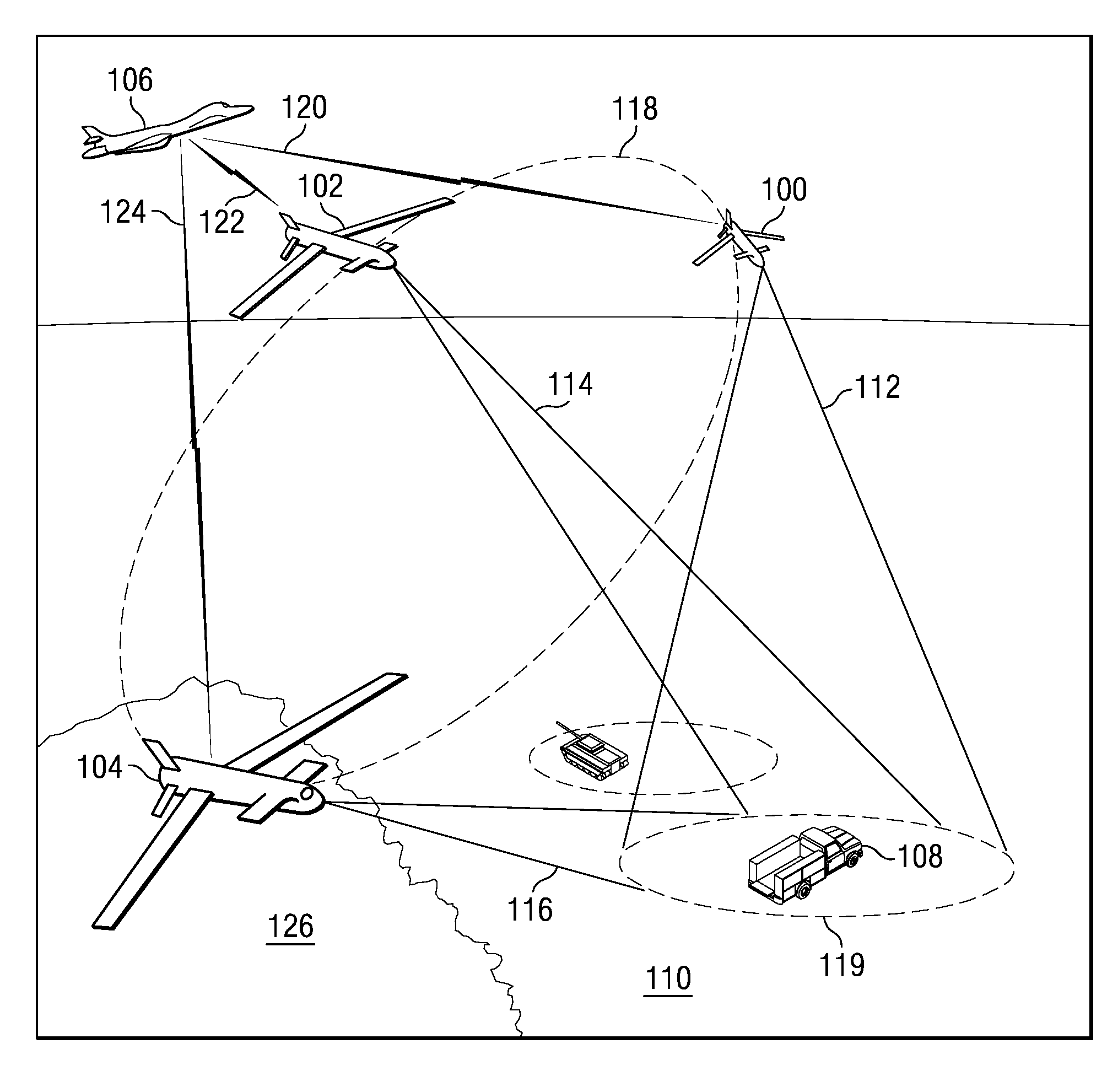
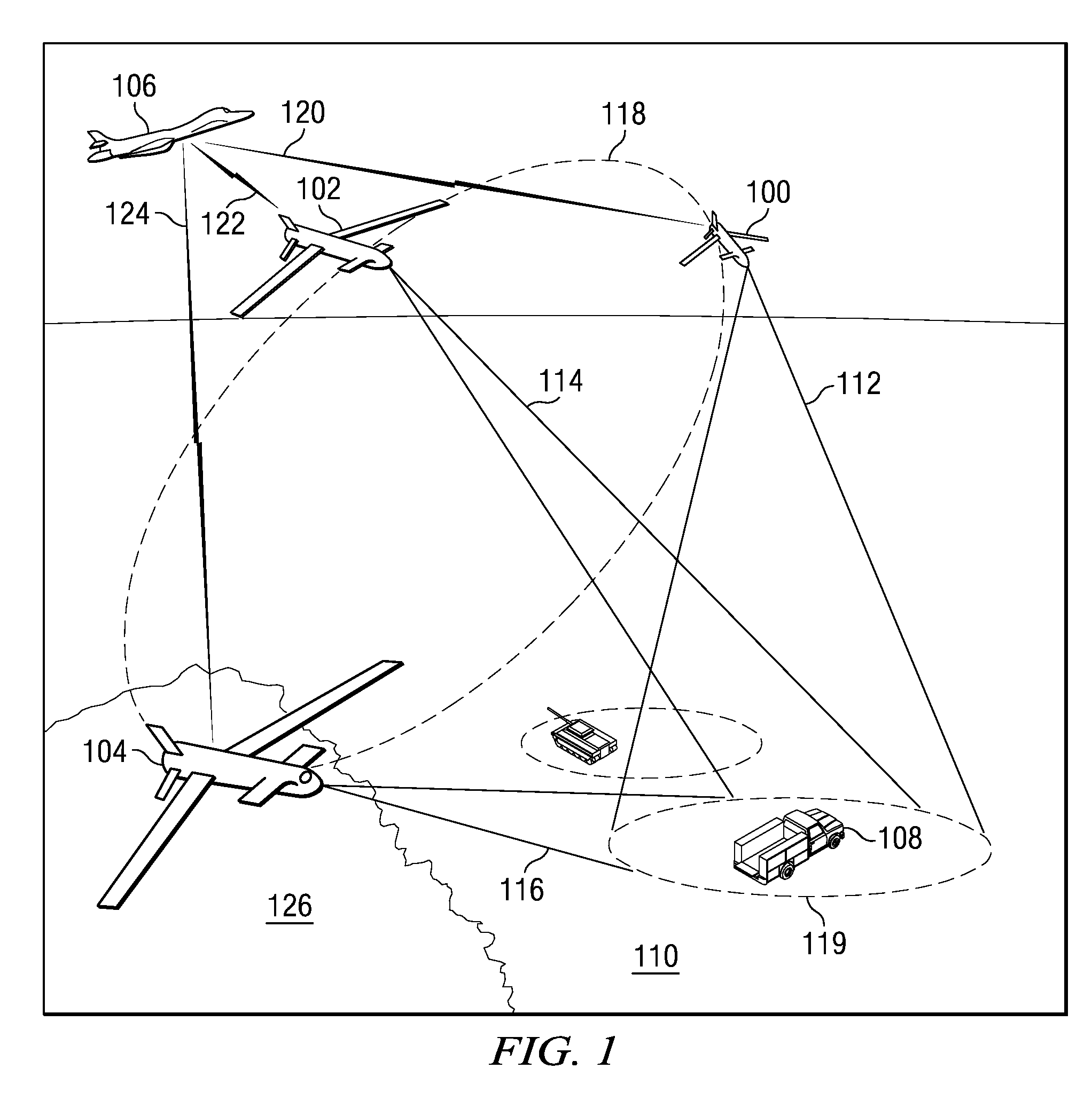
[0038]With reference now to the figures and in particular with reference to FIG. 1, a system for creating a three dimensional image of a target object is depicted in accordance with an advantageous embodiment. In this example, the system includes a coordinated network centric data collection system and a central node. The coordinated network centric data collection system contains nodes in the form of unmanned aerial vehicle (UAV) 100, unmanned aerial vehicle 102, and unmanned aerial vehicle 104. The central node takes the form of aircraft 106 in this particular example.

[0039]Unmanned aerial vehicles 100, 102, and 104 collect data for target object 108 on ground 110. In these particular examples, the data is radar data. Radar data is generated by unmanned aerial vehicles 100, 102, and 104 projecting beams or cones of electromagnetic radiation from radar systems onto target object 108 and collecting the data that returns from those beams or cones. In this example, unmanned aerial veh...


PUM


Abstract

In accordance with an embodiment, a system includes a plurality of vehicles and a central node. The plurality of vehicles each have radar systems used to collect radar data about the target object. Each in the plurality of vehicles moves in a path to collect a portion of the radar data using a sampling map to coordinate collection of the radar data by the plurality of vehicles and communicates with every other vehicle to identify uncollected portions of the radar data. The central node is in communication with the plurality of vehicles, wherein the central node receives the radar data from the plurality of vehicles and creates a three dimensional image from the radar data received from the plurality of vehicles using a tomographic reconstruction process.

Description


Claims


Application Information

Patent Timeline
Owner THE BOEING CO
Learn More