Eureka AIR delivers breakthrough ideas for toughest innovation challenges, trusted by R&D personnel around the world.

Thermal switch calibration apparatus and methods

a technology of thermal switches and calibration apparatuses, which is applied in the direction of heat measurement, instrumentation, and calibration/seeking protective devices, etc., can solve the problems of large user interaction, range input may not contain the actual switching temperature of the switch or the upper or lower bounds of the switch's hysteresis range, and the measurement of the switching temperature may be inaccura

Active Publication Date: 2009-01-01
JOHN FLUKE MFG CO INC
View PDF5 Cites 10 Cited by
  • Summary
  • Abstract
  • Description
  • Claims
  • Application Information

AI Technical Summary

Benefits of technology

[0008]In another aspect of the invention, the first, second, and third rate are determined according to an exponentially decreasing function. In some embodiments, the first, second

Problems solved by technology

It requires a large amount of user interaction to determine and input the range.
In some instances, the range input may potentially fail to contain the actual switching temperature of the switch or the upper or lower bounds of the switch's hysteresis range.
The measured switching temperature may also be inaccurate due to variations in the rate at which the temperature is swept during testing, inasmuch as the thermal response time of the drywell and switch is not immediate.

Method used


Image

  • Thermal switch calibration apparatus and methods
  • Thermal switch calibration apparatus and methods
  • Thermal switch calibration apparatus and methods

Examples


Embodiment Construction

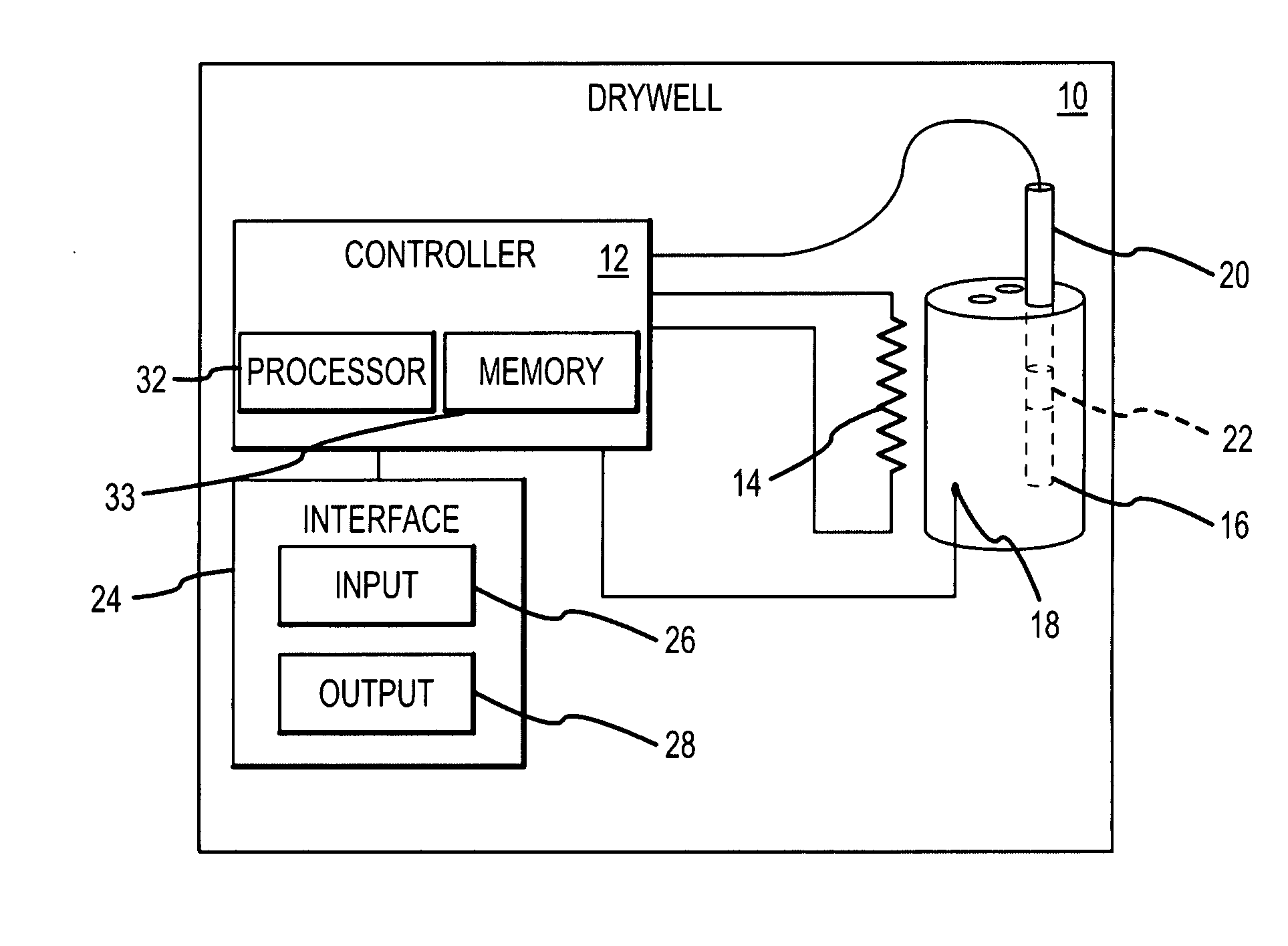
[0012]Referring to FIG. 1, in one embodiment of the invention, a drywell 10, or like device is used to determine the switching temperature of thermal switches. The drywell 10 may include a controller 12 coupled to a heating element 14. The heating element 14 may heat a receiver 16. A temperature sensor 18 may also be in thermal contact with the receiver 16 and transmit a signal corresponding to the temperature of the receiver to the controller 12 in order to provide feedback to the controller 12 to enable accurate control of the temperature of the receiver 16. The receiver 16 may be sized to receive a probe 20, or like structure, coupled to a thermal switch 22. The switch 22 may be positioned within the probe 20 such that the switch 22 is positioned within the receiver 16 during testing. Alternatively, the switch 22 may be electrically coupled to the probe 20 and located outside the receiver 16 during testing. The switch 22 may be coupled to the controller 12 such that the controlle...


PUM


Abstract

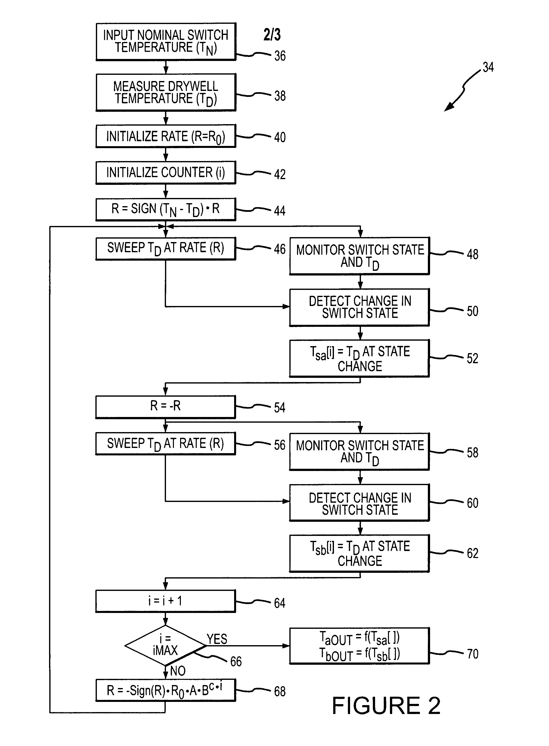
An apparatus and method for testing thermal switches is disclosed including modulating the temperature of a receiver in thermal contact with a thermal switch at a first rate within a range containing the nominal switch temperature of the thermal switch. A first temperature at which the switch changes state is recorded. The temperature is then modulated at a second rate and a second temperature at which the switch again changes state is recorded. The temperature may be modulated at a third rate slower than the second rate to determine a third temperature. The first, second, and third switch temperatures are then processed and output to an operator. The first, second, and third rates may be determined according to an exponentially decreasing function.

Description

TECHNICAL FIELD[0001]This invention relates generally to systems and methods for calibrating thermal switches.BACKGROUND OF THE INVENTION[0002]It is typical for thermometers and thermal switches to be calibrated using a drywell. Drywells may include a receiver in which a thermometer or thermal switch is inserted. A heating element and temperature sensor are in thermal contact with the receiver such that the temperature within the receiver may be accurately set. The set temperature of the drywell may then be compared to the readout temperature of the thermometer or the switching temperature of a thermal switch to determine its accuracy. In some uses, a reference thermometer is inserted within the receiver along with the thermometer or switch being calibrated, and the readout of the reference thermometer is used for calibration purposes.[0003]In prior systems thermal switches were tested by inputting to the drywell controller upper and lower boundaries of a range that contained the no...

Claims


Application Information

Patent Timeline
IPC IPC(8): G01K15/00H05B1/02G01M99/00
CPCH01H69/01H01H37/00H01H37/12H01H37/52H01H37/54
Inventor SJOGREN, ALLEN ERIKNERDRUM, ERICHARNEY, MICHAEL
Owner JOHN FLUKE MFG CO INC
Why Eureka
Eureka Blog
Learn More