
Bar code reading terminal with video capturing mode

a reading terminal and video capture technology, applied in the field of two-dimensional bar code reading terminals, can solve the problems of difficult read conditions, inability to successfully decode the bar code symbol, and large complexity of the bar code reading terminal using 2d imagers

Active Publication Date: 2009-01-01
HAND HELD PRODS
View PDF98 Cites 88 Cited by
  • Summary
  • Abstract
  • Description
  • Claims
  • Application Information

AI Technical Summary

Benefits of technology

The invention is about a system and method for diagnosing and correcting difficult bar code read conditions in bar code reading terminals. The system can automatically report the difficult read conditions by analyzing the image of the bar code and extracting the necessary data to determine the reason for the difficulty. The invention can help to improve the efficiency and accuracy of bar code reading terminals, preventing lost productivity and promoting better customer service. The system can also allow for remote control of the bar code reading terminal and facilitate video capturing and streaming.

Problems solved by technology

Bar code reading terminals using 2D imagers vary widely in complexity and capability.
Occasionally, difficult read conditions can be encountered where a 2D bar code reading terminal images a bar code symbol, but can not successfully decode the bar code symbol.
Difficult bar code read conditions can often be attributed to the technique of the operator of the bar code reading terminal, the quality of the bar code, or the bar code imager or bar code reading algorithm.
However, when difficult read conditions occur more frequently, lost productivity can cause wasted time and lost sales income.
Also, products related to difficult bar code read conditions might be set aside for re-labeling and might later be forgotten and become lost, discarded, or spoiled.
There is presently no easy way to diagnose and correct failed bar code read conditions.

Method used


Image

  • Bar code reading terminal with video capturing mode
  • Bar code reading terminal with video capturing mode
  • Bar code reading terminal with video capturing mode

Examples


Embodiment Construction

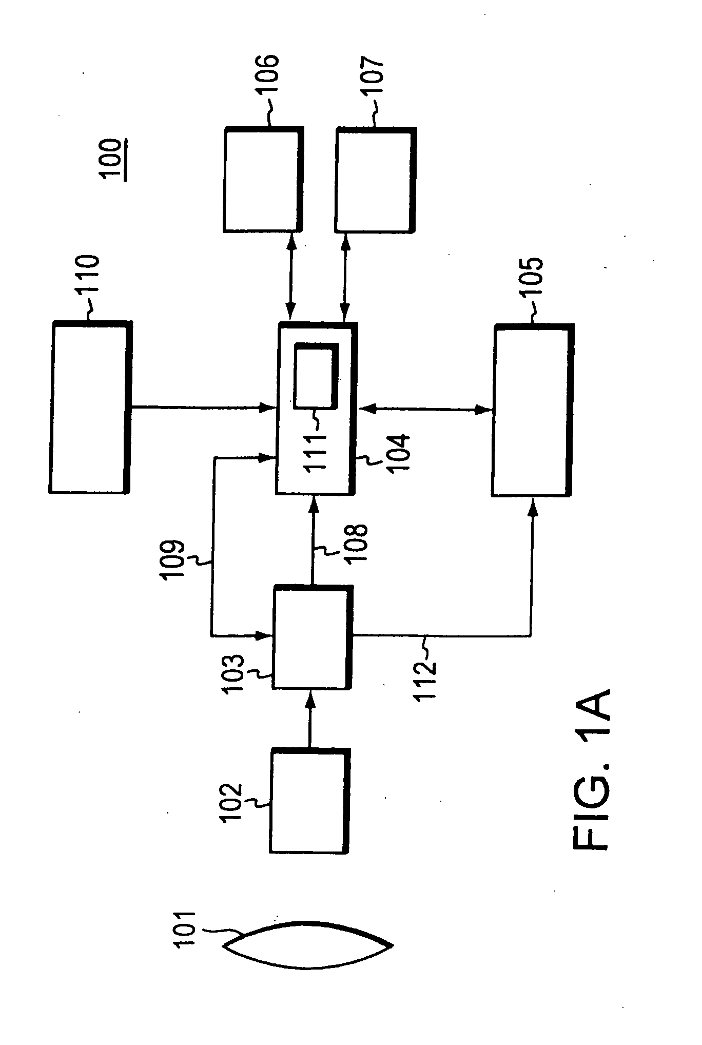
[0026]FIG. 1A shows a block diagram of one embodiment of a bar code reading terminal according to the invention. Lens assembly 101 optically focuses an image of a bar code symbol onto two-dimensional image sensor 102. Image acquisition circuit 103 acquires an electronic representation of the 2D image, herein after referred to interchangeably as a “frame.” Each frame taken on its own represents a single image. Also, each image can be typically represented as a 2D array of image pixels. Acquisition circuit 103 need not be a physically separate electronic circuit assembly. The electronic circuit performing the function of acquisition circuit 103 can be in part or entirely contained within a two-dimensional image sensor 102 physical assembly. The output of acquisition circuit 103 can typically be a raw digital representation of a frame, most typically in image map digital format. The image map digital format can be binary representation, but more typically is a gray scale or color image...


PUM


Abstract

A bar code reading terminal can, in one embodiment, include a two-dimensional image sensor and an imaging assembly. The terminal can be configured, in response to receipt of a trigger signal, to buffer a set of frames and subject each frame of the set of frames to a decode attempt. The terminal can also be configured to convert the convert the captured set of video frames into a compressed video format, and transfer the resulting video file to a file server or to one or more playback devices, in response to a user interface action, or in response to difficult read condition having been detected. The terminal can also be configured to establish two-way video- and audio-communication with a remote video- and audio-streaming device. The video capturing and streaming operation of the terminal can be controlled remotely from a playback device via web interface.

Description

FIELD OF THE INVENTION[0001]This invention relates generally to two-dimensional bar code reading terminals and more specifically to two-dimensional bar code reading terminals that are capable of video capturing and recording.BACKGROUND OF THE INVENTION[0002]Some bar code reading terminals make use of a two-dimensional (2D) imager to acquire and decode an image of a bar code symbol. The acquired image is typically decoded by an algorithm that can extract bar code data from the bar code symbol. Such bar code reading terminals can be hand held bar code reading terminals or fixed mounted bar code reading terminals on a stand or shelf as typically associated with a retail sales position.[0003]Bar code reading terminals using 2D imagers vary widely in complexity and capability. Many 2D bar code reading terminals include imaging and decoding firmware used to image the bar code symbol and to extract bar code data from the image of the bar code symbol. Some of the most basic models of 2D bar...

Claims


Application Information

Patent Timeline
Patent Type & Authority Applications(United States)
IPC IPC(8): G06K7/10
CPCG06K7/10851H04N7/173H04N21/422G06K7/1495H04N21/440236H04N21/6582H04N21/8146H04N21/44008H04N21/4223H04N21/6125H04N21/6336H04N21/85406
Inventor SEVIER, MITCHEL P.DOREN, MICHAELGOMEZ, GARRISONKOSECKI, JAMESYEAKLEY, DANIEL D.
Owner HAND HELD PRODS
Learn More