
Three-dimensional image display apparatus, method of distributing elemental images to the display apparatus, and method of displaying three-dimensional image on the display apparatus

a display apparatus and three-dimensional image technology, applied in the direction of instruments, static indicating devices, optical elements, etc., can solve the problems of limited viewing zone along the viewing direction, obvious differences in the display apparatus of multi-view systems, and observation of three-dimensional images, so as to minimize the observation angle and expand the viewing zone

Active Publication Date: 2008-12-18
HISENSE VISUAL TECH CO LTD
View PDF17 Cites 27 Cited by
  • Summary
  • Abstract
  • Description
  • Claims
  • Application Information

AI Technical Summary

Benefits of technology

The present invention provides a three-dimensional image display apparatus that can be observed in a viewing zone with a reference plane. The apparatus includes a display unit with pixels arranged in a matrix form, and a transmission control section with optical openings. The optical openings control the transmission of light rays from the elemental images. The apparatus can display a correct image and minimize the observation angle in which a pseudo image is mixed. The technical effects of the invention include providing a larger viewing zone and reducing the observation angle in which a pseudo image is mixed.

Problems solved by technology

However, the display apparatus of the multi-view system is obviously different from the II system in that the light rays from the apparatus are converged on an observation plane positioned in a visual distance.
However, when the observer moves in a transverse direction in the display apparatus of the multi-view system, and when an interval between the converging points is not sufficiently short, there is a problem that flipping of the three-dimensional image is observed or that the viewing zone along the viewing direction is limited.
In the apparatus without any glasses, there is a common problem in which a viewing region may be limited, even if the three-dimensional image can be observed without glasses.
If the concept of viewing zone is not introduced in the formation of the three-dimensional image to be displayed by the image display unit, there is a problem that an actual viewing zone is narrowed as described hereinafter.
In any case, there is a problem that the main viewing zone only for the correct image is narrow even as compared with the intermingled transitional zones, and is a limited region, which cannot substantially be used practically.
As described above, in the three-dimensional image display apparatus in which the II system is used, a problem that the viewing zone is narrow and the region including the intermingled and visually recognized correct and quasi images is large has been pointed out.
However, in a conventional three-dimensional image display apparatus, the quasi image is inevitably perceived.
Moreover, when the perceived three-dimensional image includes the quasi image, it cannot constantly be recognized that the quasi image is observed in a case where the perceived three-dimensional image includes the quasi image.
Therefore, there is a problem with the image, in situations in which the observation position is moved irregularly or when the number of pixels for displaying the two-dimensional image included in the pixels for displaying the three-dimensional parallax is changed.
Specifically, a natural movement pattern is lost.

Method used


Image

  • Three-dimensional image display apparatus, method of distributing elemental images to the display apparatus, and method of displaying three-dimensional image on the display apparatus
  • Three-dimensional image display apparatus, method of distributing elemental images to the display apparatus, and method of displaying three-dimensional image on the display apparatus
  • Three-dimensional image display apparatus, method of distributing elemental images to the display apparatus, and method of displaying three-dimensional image on the display apparatus

Examples


example 1

[0173]In the present example, only the horizontal parallax effective for the stereoscopic viewing zone is imparted. For a liquid crystal display device, QUXGA-LCD (pixel number 3200×2400, screen size 422.4 mm×316.8 mm) may be used. A minimum driving unit includes sub-pixels of R, G, B. Three sub-pixels of R, G, B arranged side by side usually form one pixel (triplet), but the sub-pixels of R, G, B arranged in a longitudinal direction were handled as one pixel in order to increase the number of horizontal pixels in the display unit of the present example. That is, parallax image information are arranged at the sub-pixel pitch in the horizontal direction. The sub-pixel has a transverse width of, for example, 44 μm and a vertical length of, for example, 132 μm. A backlight is disposed on the rear surface of the display unit. On an observer's side, transmission control sections are provided in the form of slits each having a width of, for example, 44 μm, and the slits were arranged at a...

example 2

[0177]When the elemental images are arranged in the constitution similar to that of Example 1 by the judgment method of Equation (11) in accordance with the algorithm of FIG. 19, completely the same elemental image group as that of Example 1 is obtained.

example 3

[0178]The reference distance is changed to 1.5 m in the constitution and algorithm similar to those of Example 1. The total number of parallaxes is 28, which is decreased as compared with Example 1, and the parallax number N(Xp, Xs) relating to the two-dimensional image information constituting the elemental image disposed in the vicinity of the middle disposed opposite to the center of the viewing zone in the display unit is from 6 to 21. On the other hand, for the elemental image for the slit 4 positioned second counted from the screen left end, the elemental image is generated from the N(Xp, Xs)=0 to 15 parallax images. For the elemental image for the slit 4 positioned second counted from the right end, the elemental image is generated from N(Xp, Xs)=12 to 27 parallax images. Moreover, for the sub-pixel group displaying the elemental image for the slit 4 positioned second counted from the screen left end, there are 14 sub-pixels on the left side of the normal Op positioned in the...


PUM

PropertyMeasurementUnit
refractive indexaaaaaaaaaa
sizeaaaaaaaaaa
transmissionaaaaaaaaaa

Abstract

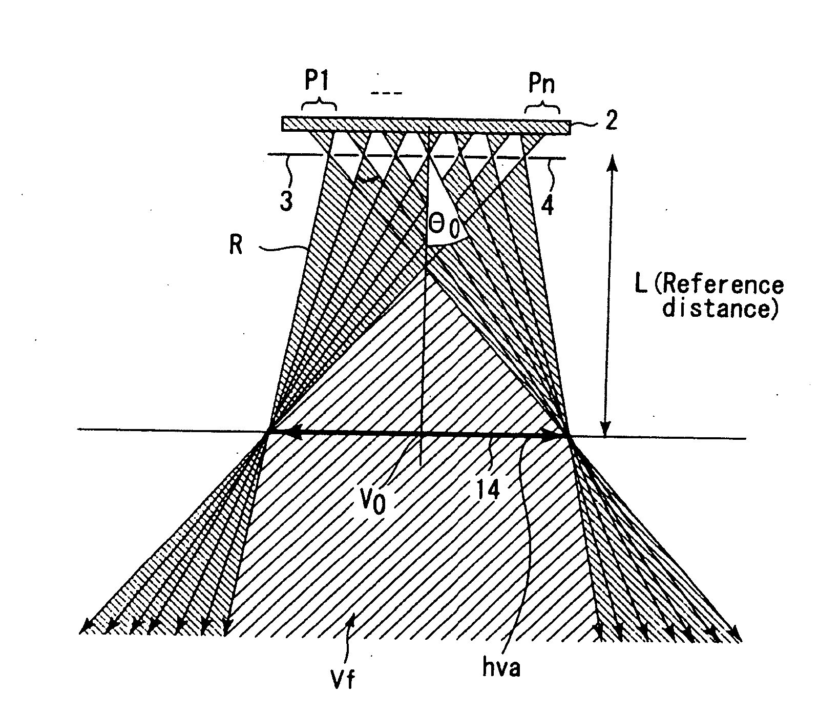
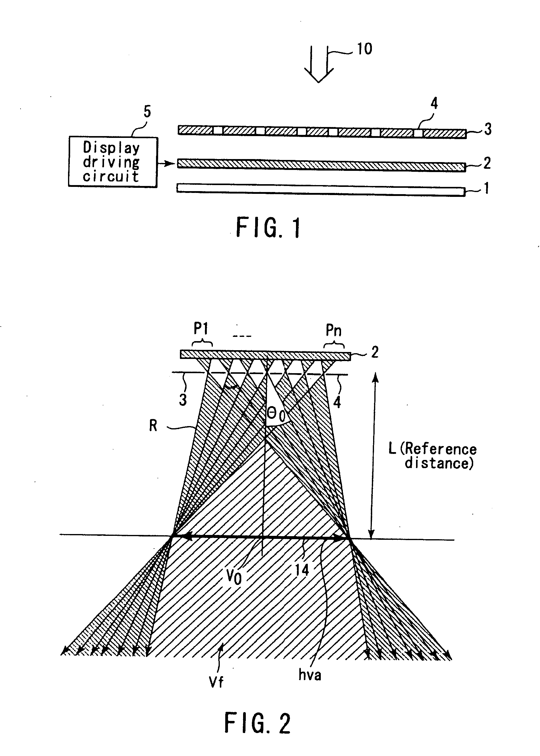
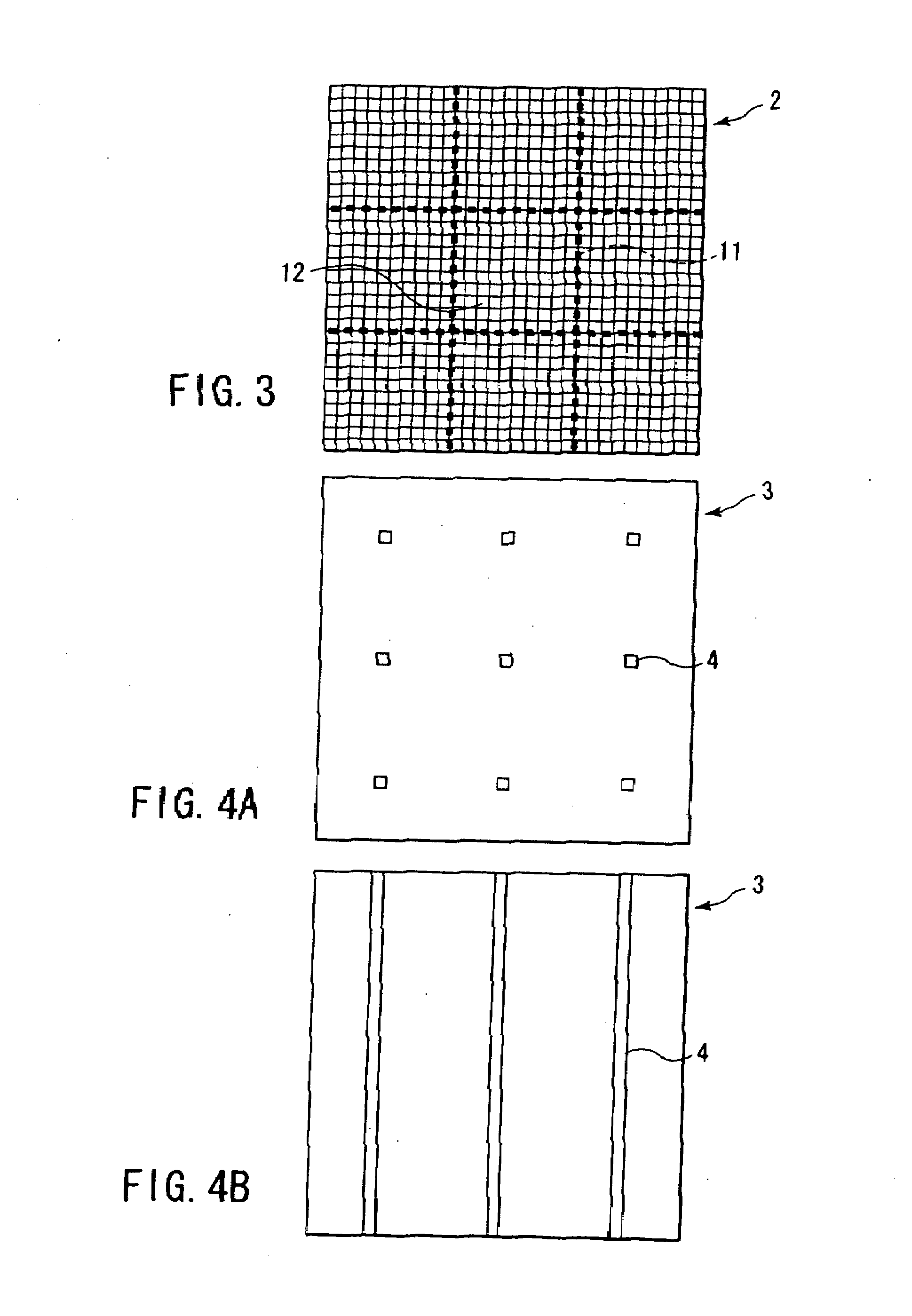
An apparatus is provided with a display unit and a optical filter. The unit has pixels arranged in a matrix form, which are groped into a first group and second groups to display two-dimensional image information constituting elemental images, the image information being obtained from different directions. The optical filter has a first optical opening opposed to the first pixel group and second optical openings opposed to corresponding one of the second pixel groups. The center of the first pixel group is coincident with the axis of the first opening, each center of the second pixel groups is deviated from corresponding one of the second opening axe, and the deviation is gradually increased depending on a distance between the first and the second pixel group centers. The light rays are directed to a reference plane from the first and second pixel groups through the first and second opening axes.

Description

CROSS-REFERENCE TO RELATED APPLICATIONS[0001]This application is a continuation of application Ser. No. 10 / 744,045 (allowed), filed Dec. 4, 2003, which is based upon and claims the benefit of priority from prior Japanese Patent Applications No. 2002-382389, filed Dec. 27, 2002 and No. 2003-047733, filed Feb. 25, 2003, all of which are incorporated herein by reference.BACKGROUND[0002]1. Technical Field[0003]The present invention relates to a display apparatus for displaying a three-dimensional image, particularly to a method of disposing elemental images to secure a maximum viewing zone, a method in which an observer can recognize deviation from the viewing zone, and an apparatus for realizing this method.[0004]2. Description of the Related Art[0005]There are various systems for displaying a three-dimensional image, and there may be roughly two methods. One of them is a system for a stereoscopic viewing using a binocular parallax, and the other method is a space image reproduction sy...

Claims


Application Information

Patent Timeline
Patent Type & Authority Applications(United States)
IPC IPC(8): G06T15/00B44C1/22G02B30/30G03B35/00G09G5/00H04N13/00
CPCG02B27/2214H04N13/0409H04N13/31G02B30/30G02B30/27
Inventor FUKUSHIMA, RIEKOHIRAYAMA, YUZOTAIRA, KAZUKI
Owner HISENSE VISUAL TECH CO LTD
Learn More