Casing coupler liner hanger mechanism

a technology of hanger mechanism and coupler, which is applied in the direction of fluid removal, tubing catchers, borehole/well accessories, etc., can solve the problems of high manufacturing cost, frequent rotation of circumference pistons, and limited maximum working pressure, and achieves easy assembly and disassembly of liner hangers. , the effect of small appreciable reduction in the useable area

Inactive Publication Date: 2008-10-23
BAKER HUGHES INC
View PDF27 Cites 7 Cited by
  • Summary
  • Abstract
  • Description
  • Claims
  • Application Information

AI Technical Summary

Benefits of technology

[0016]The casing couplers and methods of setting a liner hanger within a wellbore have the advantages of: providing an easy to assemble and disassemble liner hanger; providing a simple process for hanging the liner; p

Problems solved by technology

These designs presented a pressure rating problem in that the full circumference piston frequently had a maximum working pressure significantly lower than the mandrel which it surrounded.
Thus, this type of design limited the maximum working pressure in the string to the rating of the cylindrical piston housing assembly.
This design, however, was expensive to manufacture, had many potential leak paths in the form of the ring seals on each of the pistons wherein each slip required two pistons.
The design in U.S. Pat. No. 5,417,288 also did not provide for flexibility for changed conditions downhole which could require additional force to set the slips.
Therefore, these liner hange

Method used


Image

  • Casing coupler liner hanger mechanism
  • Casing coupler liner hanger mechanism
  • Casing coupler liner hanger mechanism

Examples


Embodiment Construction

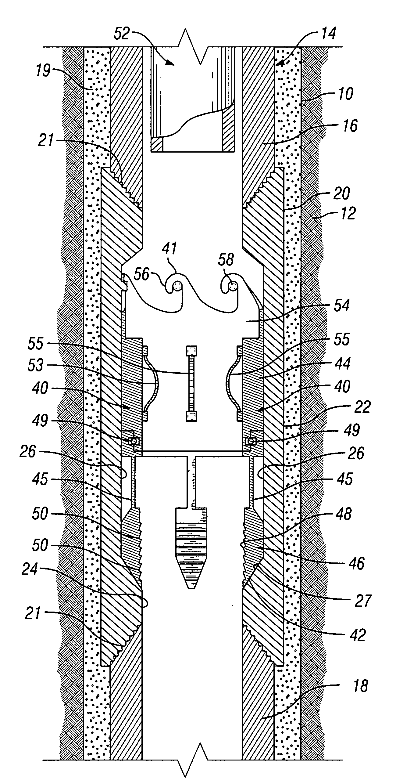
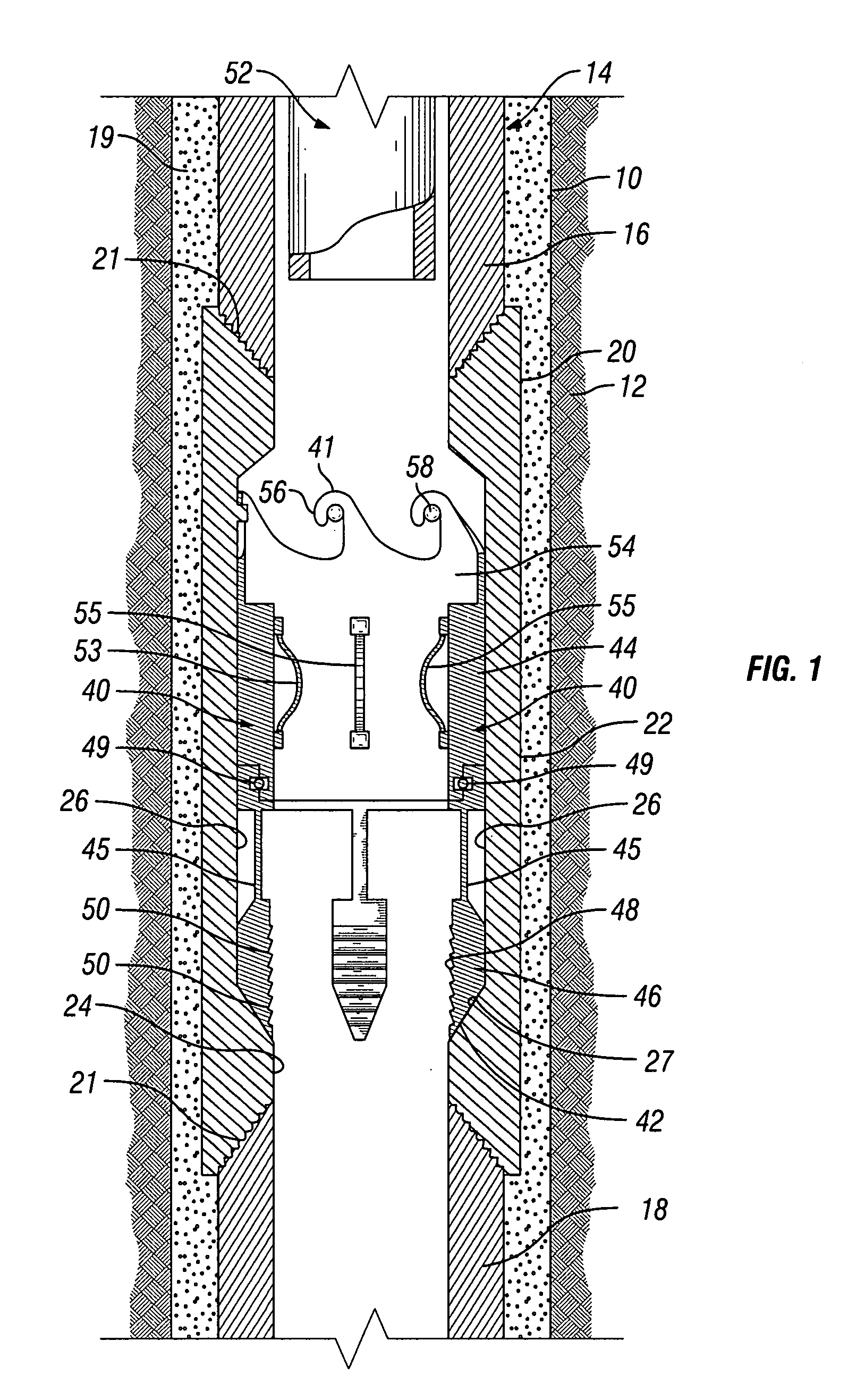
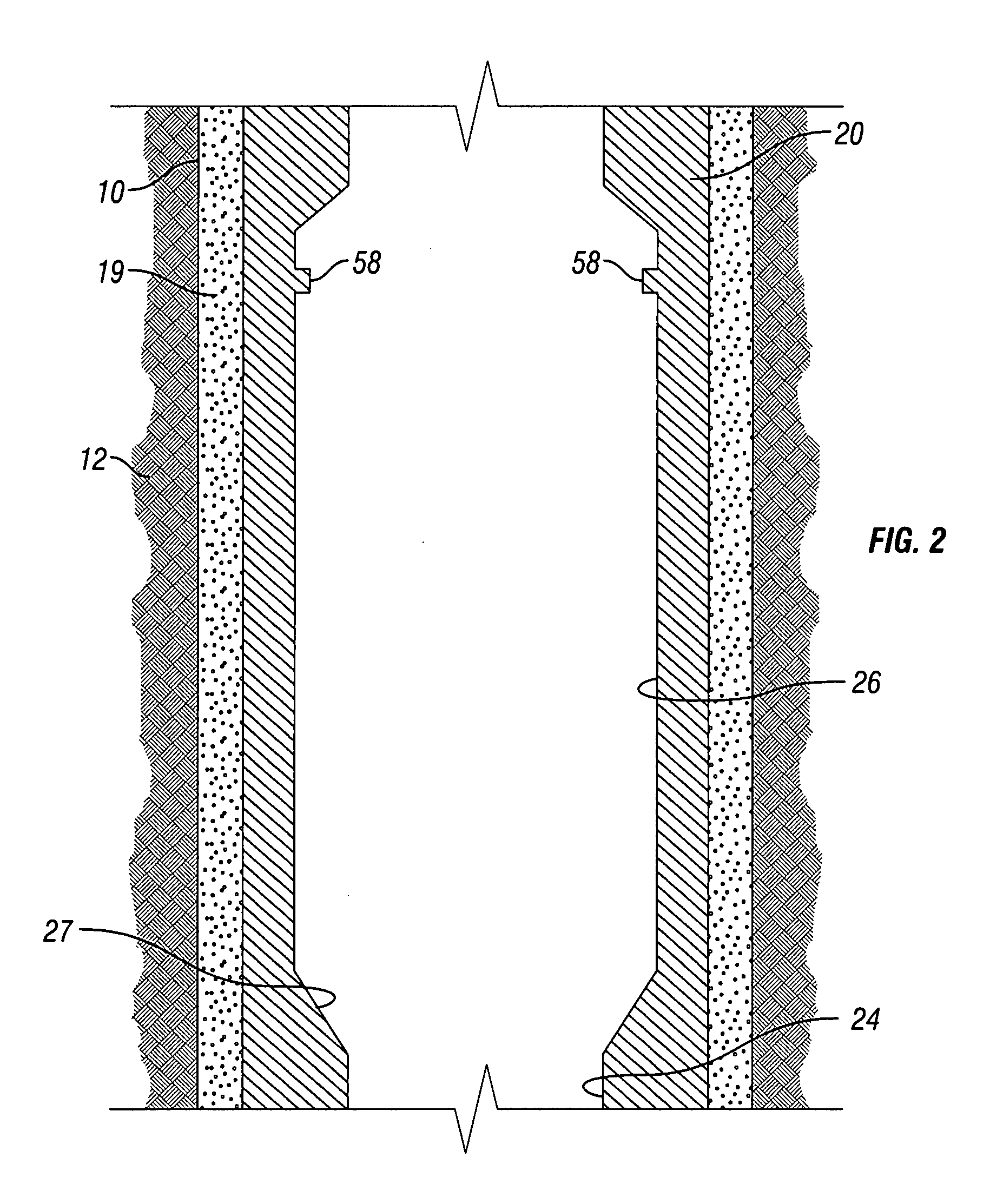
[0034]Referring now to FIGS. 1-9, the invention is described broadly with respect to wellbore 10 disposed within formation 12 having casing string or casing 14 disposed therein. Casing string 14 includes upper casing section 16 and lower casing section 18. Upper casing section 16 is supported at its upper end, either directly or indirectly though another piece of casing or by a wellhead assembly. Collar or coupler 20 connects upper casing section 16 with lower casing section 18 using any method or device known to persons of ordinary skill in the art, such as by threads 21. Casing string 14 and coupler 20 are secured within formation 12 by cement 19. Upper casing section 16 and lower casing section 18 have the same inner and outer diameters.

[0035]Coupler 20 includes an outer wall surface 22 defining an outer diameter and an inner wall surface 24. Inner wall surface 24 includes recess or pocket 26 defined by an enlarged inner diameter between two smaller inner diameters—one above and ...


PUM


Abstract

A liner hanger has a housing with a pocket disposed on an inner wall surface and a slip slidingly engaged within the pocket. The liner hanger housing is secured in the string of casing. Both a setting mechanism and a liner engagement member are connected to the slips and are also located in the pocket. A releasable latching mechanism maintains the slips in the run-in position until the releasable latching mechanism is actuated. As the liner is moved through the casing coupler, the liner engagement member engages the liner through frictional force to cause the setting mechanism to move with the liner so that the latching mechanism can be disengaged and the slips can move axially downward. As the setting mechanism moves downward, the slips move radially inward and grip the liner.

Description

BACKGROUND[0001]1. Field of Invention[0002]The invention is directed to couplers or collars having one or more axially movable slips disposed therein for connecting oil and gas well casing and for hanging a liner within the casing.[0003]2. Description of Art[0004]A liner is a tubular member that is usually run inside of wellbore casing of an oil or gas well and suspended within the wellbore casing. Liners are typically secured within a wellbore by toothed slips that are located on liner hangers. The slips are set by axially translating them with respect to the liner hanger mandrel or housing. As the slips are translated axially, they are cammed radially outward by a ramped surface that is fashioned into the mandrel. As the slips move radially outward, the toothed surfaces of the slip will bitingly engage the inner wall surface of the wellbore casing. This type of arrangement is shown, for example, in U.S. Pat. No. 4,497,368 in which slips are radially expanded by riding up over cone...

Claims


Application Information

Patent Timeline
IPC IPC(8): E21B43/10
CPCE21B23/004E21B23/01E21B43/10
Inventor FAY, PETER J.LYNDE, GERALD D.O'MALLEY, EDWARD J.
Owner BAKER HUGHES INC
Why Eureka
Try Eureka