
Portable Manway Cover Hinge Device

a hinge device and manway cover technology, applied in the field of manway covers, can solve the problems of re-certification adversely affecting the integrity/reliability of the equipment structure,

Active Publication Date: 2008-10-23
UNIVERSAL HINGE CORP
View PDF39 Cites 8 Cited by
  • Summary
  • Abstract
  • Description
  • Claims
  • Application Information

AI Technical Summary

Benefits of technology

[0012]It is an object of the present invention to provide a portable manway cover hinge device that can be quickly and easily installed to remove and / or install, support, and / or store a manway cover. It is another object of the present invention to provide a portable manway cover hinge device that can be used in confined or congested areas to remove and / or install, support, and / or store a manway cover. It is a further object of the present invention to provide a portable manway cover hinge device that does not require its use from the floor to remove and / or install, support, and / or store a manway cover. It is still another object of the present invention to provide a portable manway cover hinge device that is portable and that can be used as required in different locations to remove and / or install, support, and / or store a manway cover. It is yet another object of the present invention to provide a portable manway cover hinge device that one man can handle and install for removing and / or installing, supporting, and / or storing a manway cover.
[0018]One of the main advantages of the present invention is that the present invention does not require welding of the hinge device to the equipment with the removable cover.

Problems solved by technology

Given that welding to some equipment structures (pressure vessels and the like) may adversely affect the integrity / reliability of the equipment structure, or re-certification of the equipment structure.

Method used


Image

  • Portable Manway Cover Hinge Device
  • Portable Manway Cover Hinge Device
  • Portable Manway Cover Hinge Device

Examples


Embodiment Construction

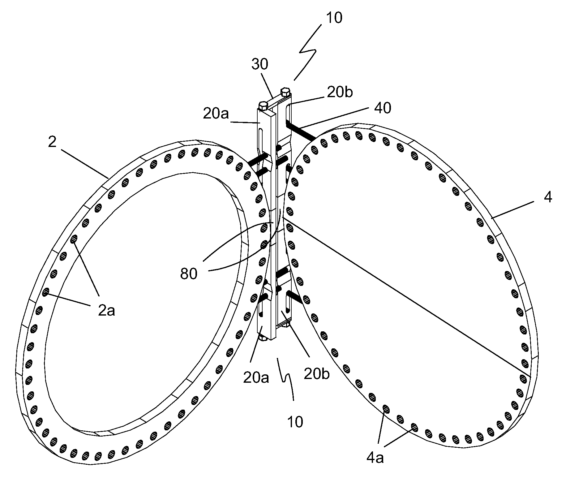
[0033]The preferred embodiment(s) of the present invention is illustrated in FIGS. 1-14. FIG. 1 illustrates the use of a portable manway cover hinge device 10 on a manway. Hinge device 10 includes a pair of elongated hinge members 20, a linkage member 30 and a plurality of support members 40. One of the elongated hinge members 20 is connected to a manway cover flange 2 and the other of the elongated hinge members 20 is connected to the peripheral edge of manway cover 4. Linkage member 30 is pivotally connected to the pair of elongated hinge members 20 and configured to swing manway cover 4 away from manway opening 6 providing access to the inside of the manway structure. A plurality of pins 60 secure a plurality of support members 40 to a plurality of bolt holes 2a and 4a in manway flange 2 and manway cover 4, respectively.

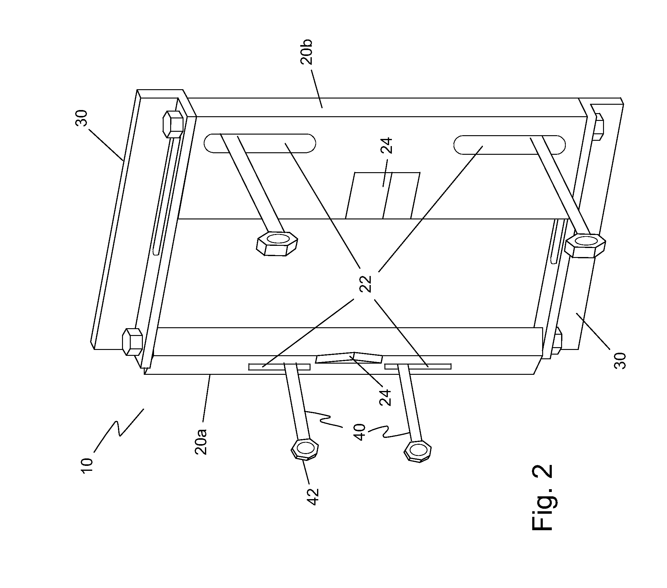
[0034]FIG. 2 illustrates the portable manway cover hinge device 10. Hinge device 10 includes a pair of elongated hinge members 20 comprising a flange hinge member...


PUM


Abstract

A portable manway hinge device has a pair of elongated hinge members where each hinge member has a pair of longitudinally-aligned, elongated apertures, a support member slidably connected to each of the elongated apertures where the support member has a pin receiving end, and a linkage member pivotally connected to each of the pair of elongated hinge members.

Description

BACKGROUND OF THE INVENTION[0001]1. Field of the Invention[0002]The present invention relates generally to “manway” covers for access to enclosed spaces such as tanks, conduits, storage areas, heat exchanger tubes. Particularly, the present invention relates to mechanisms to assist in the removal of “manway” covers. More particularly, the present invention relates to mechanisms for handling the removal and installation of “manway” covers that are too heavy to be handled by an unaided individual.[0003]2. Description of the Prior Art[0004]Manway covers are typically large, heavy, metal plates that are bolted to an opening. For purposes of the present invention, the definition of “manway covers” expressly means any heavy covers or closures used on pressure vessels, vacuum vessels, atmospheric vessels, heat exchangers, heat exchanger channel covers, heat exchanger channels, heat exchanger bonnets, or any type of blanking plate and is not construed to be limited to only covers used on op...

Claims


Application Information

Patent Timeline
IPC IPC(8): E05D7/06
CPCB65D90/10Y10T16/5327F16J13/20F16J13/18
Inventor DEPIETRO, EDWARD A.POREBSKI, JAMES J.
Owner UNIVERSAL HINGE CORP
Learn More