
Portable Lift, support, removal and/or installation system and method

a technology for lifting and supporting, which is applied in the direction of cranes, etc., can solve the problems of affecting the safety of workers, and presenting additional safety hazards in the prior, so as to eliminate rigging

Inactive Publication Date: 2004-04-01
POREBSKI JAMES J +1
View PDF21 Cites 0 Cited by
  • Summary
  • Abstract
  • Description
  • Claims
  • Application Information

AI Technical Summary

Benefits of technology

[0041] 1. Provide a device that can be quickly and easily installed to remove and / or install, support, and / or store an item or component.
[0051] Overall the present invention can in some exemplary embodiments provide one or more of the following advantages over the prior art:
[0053] 2. Worker safety is increased by eliminating dangerous procedures often used in a plant environment. A typical example of a dangerous procedure includes leaving one bolt in a manway cover at the 6 o'clock position and allowing the cover to "swing down." Reinstallation often requires multiple individuals to "swing the cover up", pivoting it on the one bolt that was left in and "catching" another bolt hole to secure the cover. This often results in personal injury when the cover catches someone's finger in the process or abruptly swings down and strikes an individual. The present invention eliminates this unsafe practice and affords a safe method in which components may be removed and reinstalled.
[0057] 6. The present invention eliminates rigging to remove and reinstall components.
[0058] 7. The present invention eliminates cranes, hoists, and / or other heavy machinery to remove and reinstall components.

Problems solved by technology

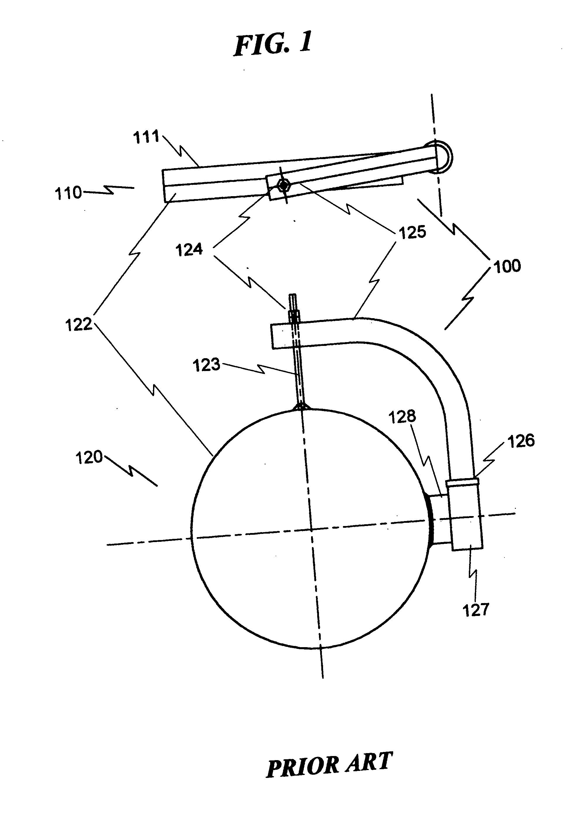
The deficiencies of the prior art in handling attached manway covers, in which the cover is removed and placed to the side of the equipment fixture.
This is a hazardous operation, as the manway cover could fall or otherwise injure the maintenance personnel.
However, in many circumstances this infrastructure is not available and must be fabricated.
This presents an additional safety hazard in the prior art.
This technique can cause injury, especially if the manway cover is heavy.

Method used


Image

  • Portable Lift, support, removal and/or installation system and method
  • Portable Lift, support, removal and/or installation system and method
  • Portable Lift, support, removal and/or installation system and method

Examples


Embodiment Construction

Embodiments are Exemplary

[0086] While this invention is susceptible of embodiment in many different forms, there is shown in the drawings and will herein be described in detailed preferred embodiment with the understanding that the present disclosure is to be considered as an exemplification of the principles and is not intended to limit the broad aspect to the embodiment illustrated.

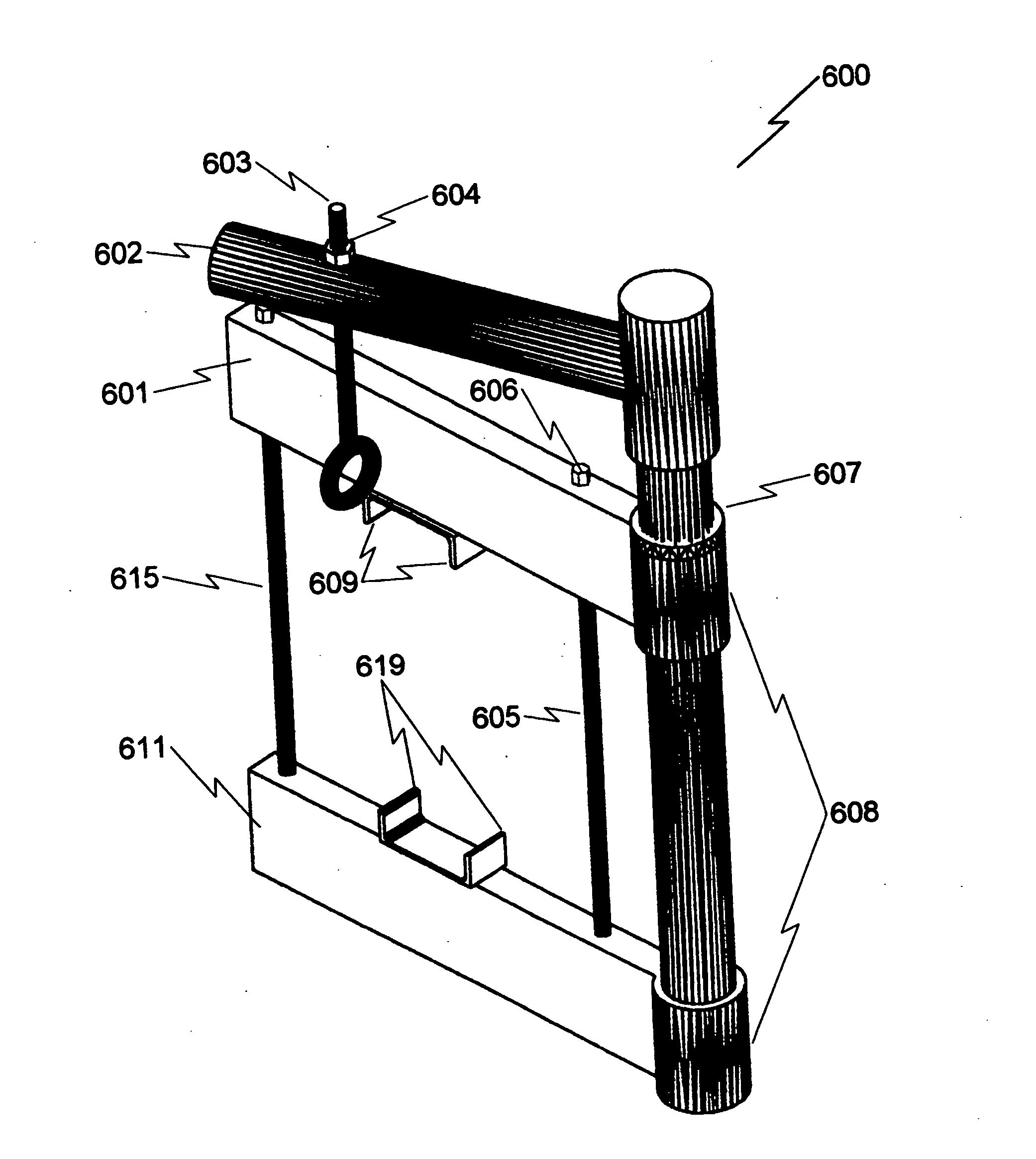
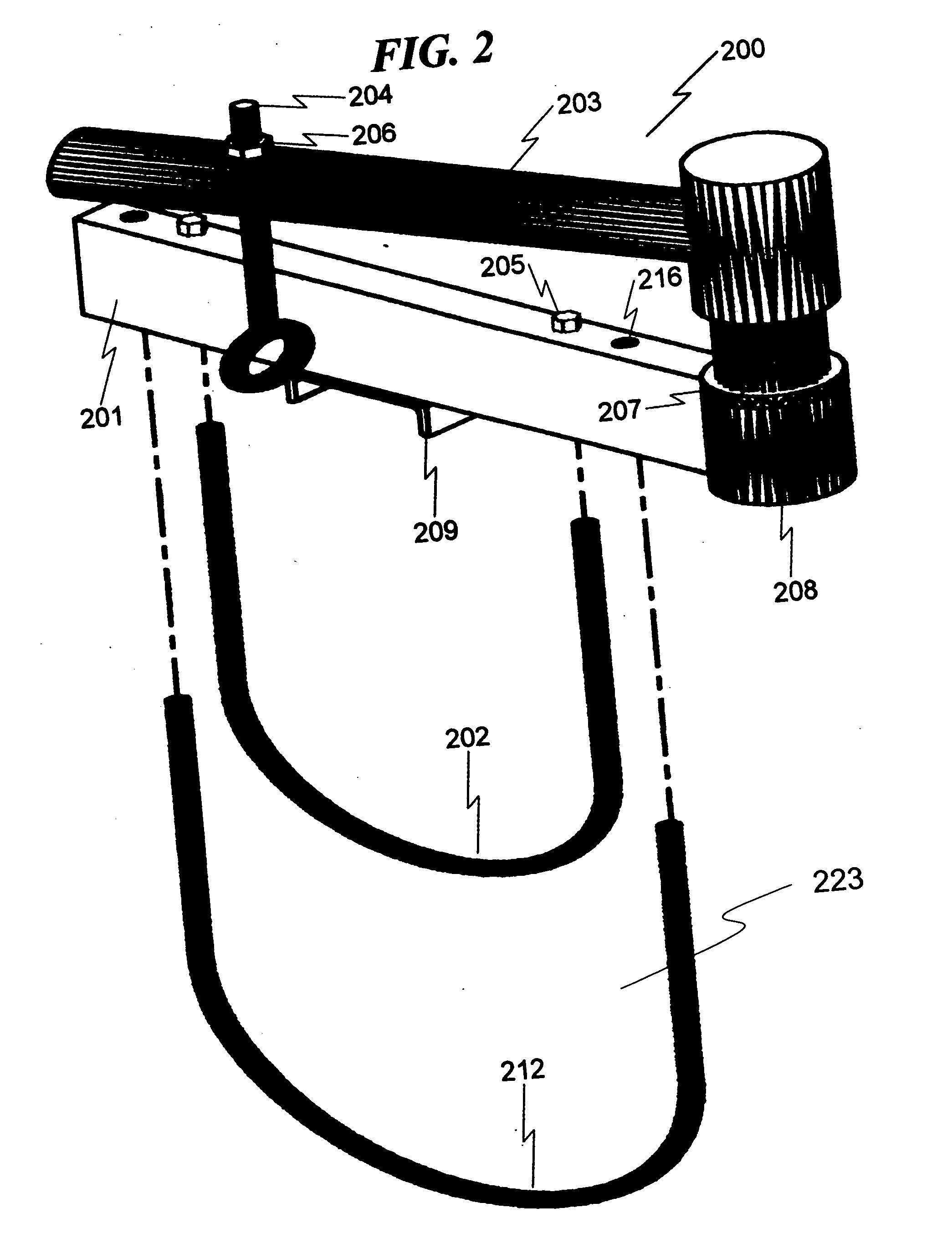
[0087] The numerous innovative teachings of the present application will be described with particular reference to the presently preferred embodiments, wherein these innovative teachings are advantageously applied to the particular problems of a portable lift, support, removal, and / or installation system and method. However, it should be understood that these embodiments are only examples of the many advantageous uses of the innovative teachings herein. In general, statements made in the specification of the present application do not necessarily limit any of the various claimed inventions. Moreover, so...


PUM


Abstract

A method for portable lift, support, and / or installation is disclosed which permits and enables these various functions without the need for external crane / lift machinery. The method includes attaching a removable swingarm assembly around an object extension of a structure, inserting a swingarm into a swingarm sleeve on the removable swingarm assembly, positioning the swingarm wherein an object support assembly on the swingarm is adjacent a removable object, attaching the object support assembly to the removable object, disconnecting the removable object from the structure, and pivoting the swingarm causing the removable object to be moved away from the structure.

Description

[0001] This application is a divisional application of Ser. No. 09 / 481,599 filed on Jan. 12, 2000.[0002] The present invention relates to field installation and removal of movement objects / components from equipment fixtures and the like. These applications are typically within industrial environments where the movement objects are large, heavy, and difficult to manipulate.[0003] This invention relates generally to the removal and / or installation of equipment from a wide variety of locations. It provides the necessary support mechanism, lifting mechanism and temporary storage of the equipment to be removed and / or installed. In addition, the invention is portable in nature and can be moved from location to location as needed.DESCRIPTION OF THE PRIOR ARTOverview[0004] Generally, power plants, co-generation power plants, chemical plants, petrochemical plants, refineries, dairies, tank farms, gas storage facilities, liquid natural gas storage facilities, manufacturing facilities and / or a...

Claims


Application Information

Patent Timeline
IPC IPC(8): B66C23/20
CPCB66C23/203
Inventor POREBSKI, JAMES J.DEPIETRO, EDWARD A.
Owner POREBSKI JAMES J
Learn More