
Underwater Detection Device

a detection device and water-covered technology, applied in seismology, instruments, seismology for water-covered areas, etc., can solve the problem of bubbles in water inducing problems in forward detection sonar, and achieve the effect of more surely identified

Inactive Publication Date: 2008-10-02
FURUNO ELECTRIC CO LTD
View PDF5 Cites 23 Cited by
  • Summary
  • Abstract
  • Description
  • Claims
  • Application Information

AI Technical Summary

Benefits of technology

[0007]The present invention has been implemented in view of the foregoing problem, and has the objective to provide an underwater detection device that can identify an echo based on bubbles in water and prevent misidentification on a display screen.
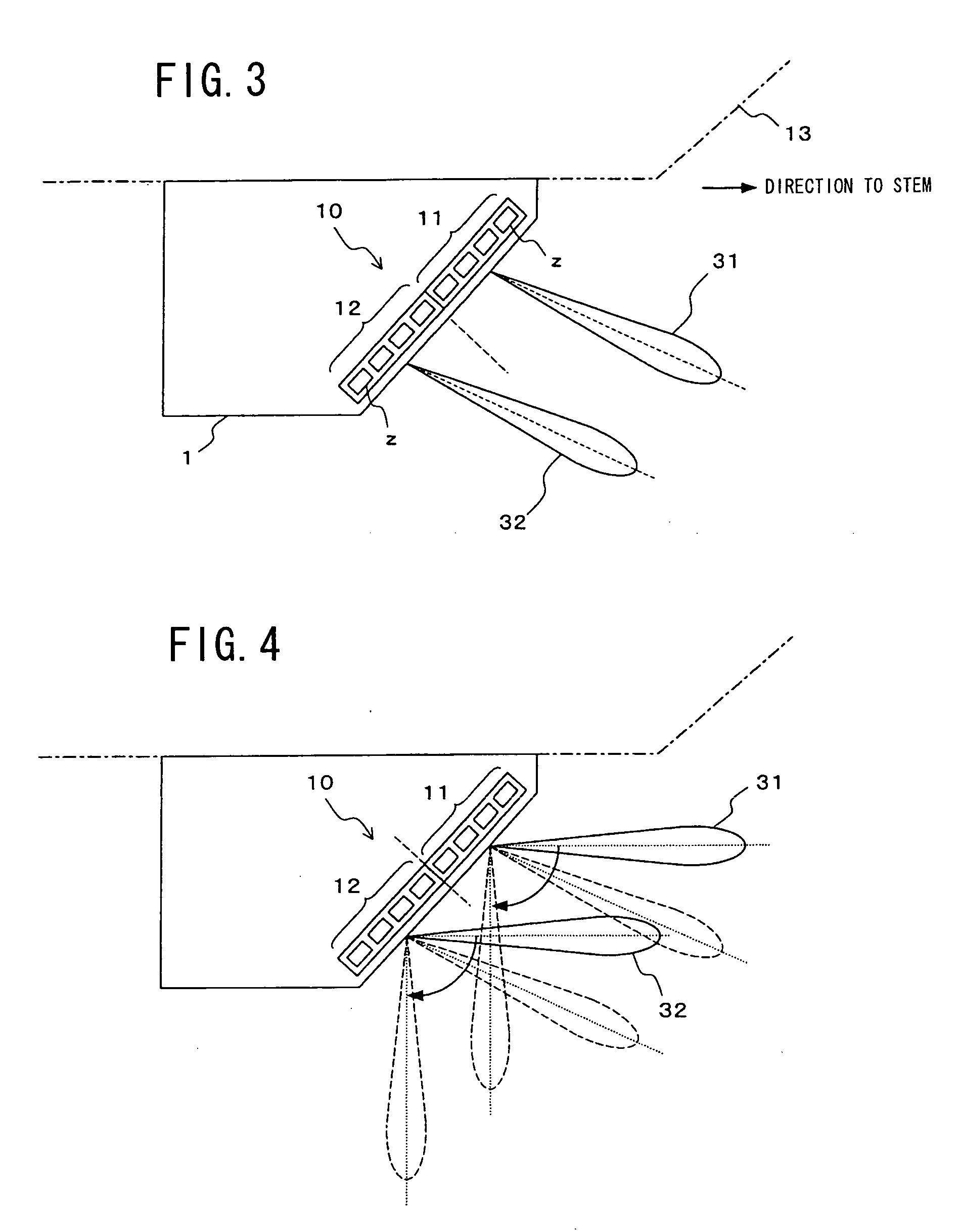
[0009]According to the present invention, an echo from a fixed target and an echo from a cluster of bubbles are discriminated from each other (identified) by utilizing the fact that the difference between the phase difference of the echo detected by the first and second reception beams formed in some direction and the phase difference of the echo detected by the first and second reception beams formed in the direction rotated from the former direction by the predetermined angle converges within a predetermined range in the case of the echo from a single fixed target, and the difference concerned is out of the predetermined range due to various kinds of causes such as disturbance of phase, etc. in the case of the echo from the cluster of bubbles. That is, a threshold value is set to the difference of the phase differences, and an echo is displayed only when the difference concerned is within a predetermined range. Accordingly, even when the signal intensity of the echo based on bubbles is large, it is not displayed with the original color corresponding to the signal intensity, and thus there is no risk that the echo based on bubbles is misidentified as an echo based on a breakwater or the like, so that the echo can be surely identified.
[0010]In the present invention, when it is judged by the judging unit that the value of the difference of the phase differences is not within the predetermined range, the display of the echo concerned may be disabled. Accordingly, the echo based on bubbles is never displayed on the display screen, and thus there is no risk that the echo based on bubbles is misidentified as another echo, so that the echo can be more surely identified.
[0011]Still furthermore, in the present invention, when it is judged by the judging unit that the value of the difference of the phase differences is not within the predetermined range, the echo concerned may be displayed with a specific color tone. Accordingly, for example by displaying the echo based on bubbles with pale color of the sea, the echo concerned can be easily identified as the echo based on bubbles, and also there is no risk that the echo based on bubbles is misidentified as another echo because it is displayed with inconspicuous color.
[0012]According to the present invention, the echo based on bubbles is not displayed with the original color corresponding to the signal intensity thereof, and thus there is no risk that the echo based on bubbles is misidentified as an echo based on a shallow place, a breakwater or the like, so that the echo can be surely identified.

Problems solved by technology

Existence of bubbles in water induces a problem in the forward detection sonar.

Method used


Image

  • Underwater Detection Device
  • Underwater Detection Device
  • Underwater Detection Device

Examples


Embodiment Construction

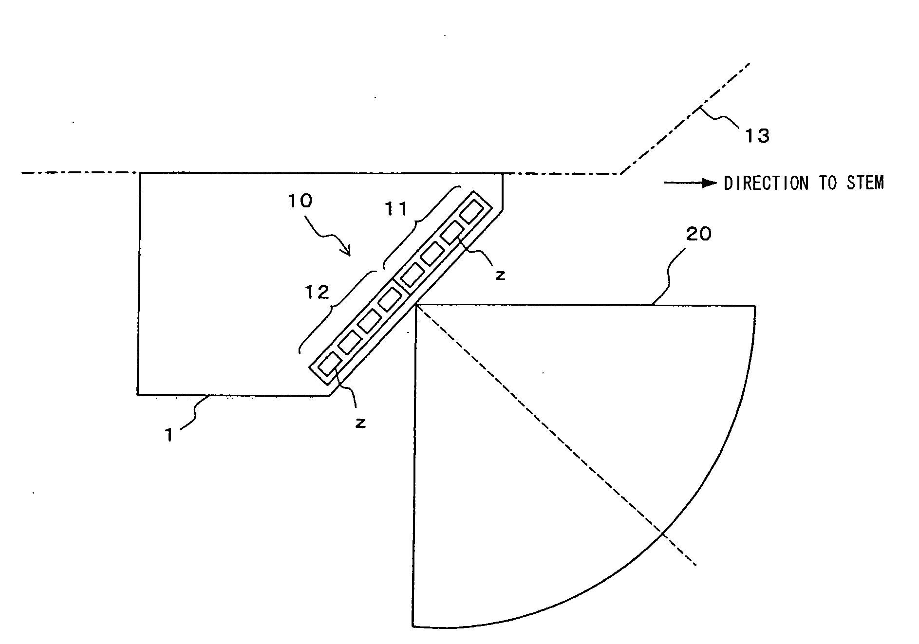
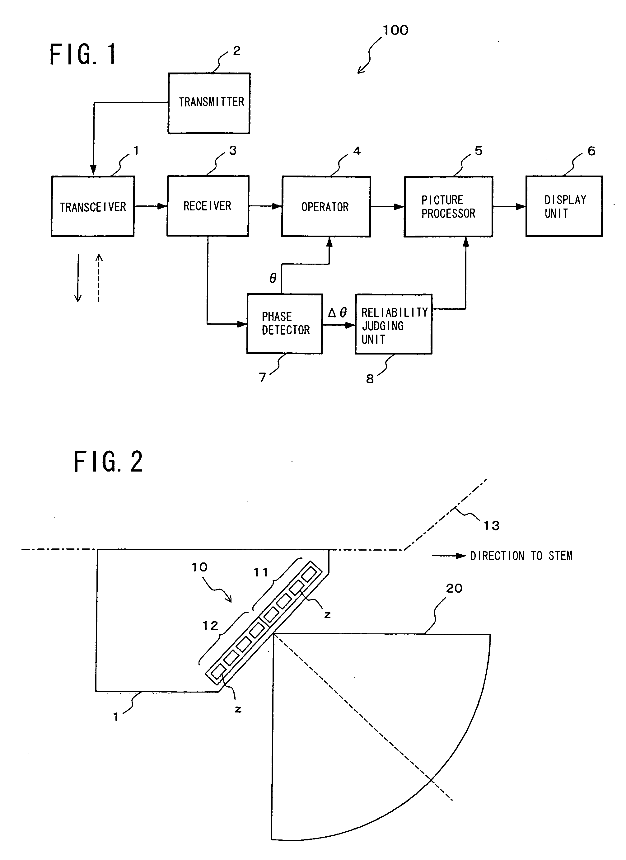
[0025]FIG. 1 is a block diagram showing an embodiment of an underwater detection device according to the present invention. In the following description, a forward detection sonar 100 is used as the underwater detection device. In FIG. 1, reference numeral 1 represents a transceiver for transmitting ultrasonic waves to a predetermined area in water and receiving an echo reflected from a target, reference numeral 2 represents a transmitter for generating a transmission signal to be supplied to the transceiver 1, and reference numeral 3 represents a receiver for receiving an echo which is received by the transceiver 1 and converted to an electrical signal, and also forming a reception beam described later. Reference numeral 4 represents a calculator for executing a predetermined calculation on the basis of information of the echo received by the receiver 3, reference numeral 5 represents a picture processor for executing the processing of displaying pictures of an echo on the basis of...


PUM


Abstract

In an under water detection for detecting the phase difference of an echo by two reception beams according to a split beam method, the difference Δθ between the phase difference of an echo detected by first and second reception beams formed in some direction and the phase difference of the echo detected by first and second reception beams which is formed in a direction rotated from the former direction concerned by a predetermined angle is detected by a phase detector. A reliability judging unit judges whether the difference Δθ detected by the phase detector is within a predetermined range or not. If the difference Δθ is within the predetermined range, an echo is displayed on a display unit. If the difference Δθ is not within the predetermined range, the echo is displayed with a specific color tone or the echo is not displayed.

Description

BACKGROUND OF THE INVENTION[0001]1. Field of the Invention[0002]The present invention relates to an underwater detection device such as a forward detection sonar, and particularly to an underwater detection device using a split beam type transducer array.[0003]2. Description of the Related Art[0004]A forward detection sonar is an underwater detection device for measuring the direction and distance to an obstacle and displaying pictures of the obstacle in order to prevent occurrence of a collision accident or a trouble of navigation before something happens when there is some obstacle such as a shallow place, a breakwater, a driftwood or the like ahead of a ship. Such a forward detection sonar is mounted on the hull of a ship, and transmits / receives ultrasonic waves in a 90° fan-shaped area going from the horizontal direction parallel to the sea level to the vertical direction below the ship, whereby a target in this range is detected. For example, when a breakwater exists ahead of t...

Claims


Application Information

Patent Timeline
Patent Type & Authority Applications(United States)
IPC IPC(8): G01V1/38
CPCG01S7/539G01S15/42G01S15/87G01S15/89G01S15/96
Inventor DUBUIS, JEROMEMAENO, HITOSHI
Owner FURUNO ELECTRIC CO LTD
Learn More