Over-the-wire catheter with lateral access

a catheter and lateral access technology, applied in the field of catheters, can solve the problems that the particular catheter does not necessarily have the structural wherewithal to effectively navigate the vasculature on its own, and achieve the effect of facilitating the advancement of the catheter

Inactive Publication Date: 2008-09-18
SCHATZ RICHARD A
View PDF25 Cites 13 Cited by
  • Summary
  • Abstract
  • Description
  • Claims
  • Application Information

AI Technical Summary

Benefits of technology

[0006]A catheter system in accordance with the present invention includes a catheter that is specifically designed to facilitate the advancement of the catheter over a guide wire and into the vasculature of a patient. To do this, the present invention provides a catheter that permits changes in the structural interaction of the catheter with the guide wire. Specifically, the catheter of the present invention allows the operator to selectively change between an over-the-wire and a monorail method of guide wire usage. More generally, the catheter system of the present invention permits an over-the-wire type operation, a monorail type operation, or a hybrid combination of the two. It also allows the operator access to the guide wire, at selected locations along the length of the catheter.
[0007]Structurally, the catheter of the present invention has a proximal end and a distal end with a main lumen that extends along the length of the catheter between the two ends. Also, the catheter has a distal bracket and a proximal bracket. Specifically, the distal bracket is formed on the catheter to extend from the distal end of the catheter in a proximal direction. It surrounds and defines a distal guide wire lumen. Similarly, the proximal bracket is formed on the catheter to extend from the proximal end of the catheter in a distal direction. It surrounds and defines a proximal guide wire lumen. A consequence of this is that a lateral access is established between the distal bracket and the proximal bracket. In order to help stabilize a guide wire in the lateral access, the surface of the catheter between the distal bracket and the proximal bracket can be formed with a groove that is dimensioned to receive the guide wire therein.
[0009]In an alternate embodiment of the present invention, the catheter can be formed with a central bracket that is located between the distal bracket and the proximal bracket. For this embodiment, the central bracket will effectively divide the lateral access into a proximal lateral access and a distal lateral access. Structurally and functionally, the central bracket is essentially the same as either the proximal bracket or the distal bracket.

Problems solved by technology

Therefore, as a practical matter, a particular catheter may not necessarily have the structural wherewithal to effectively navigate the vasculature on its own.

Method used


Image

  • Over-the-wire catheter with lateral access
  • Over-the-wire catheter with lateral access
  • Over-the-wire catheter with lateral access

Examples


Embodiment Construction

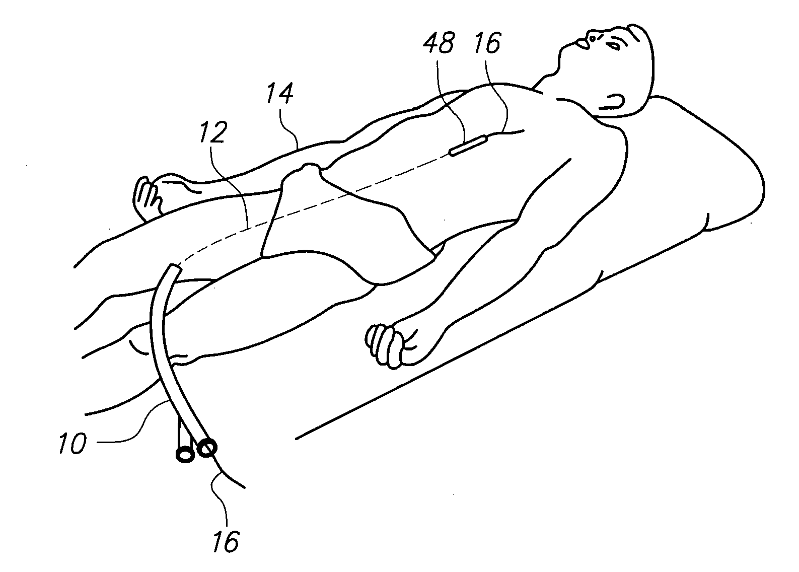
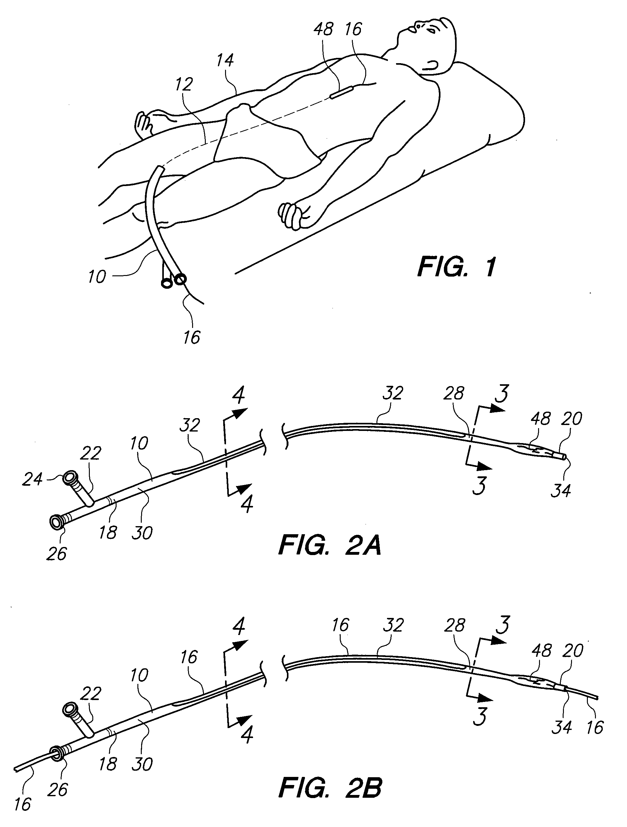
[0020]Referring initially to FIG. 1 a catheter in accordance with the present invention is shown and designated 10. As shown, the catheter 10 has been advanced along a path 12 through the vasculature of a patient 14 over a guide wire 16. The actual structure for the catheter 10 will be best seen in FIG. 2A.

[0021]In FIG. 2A it will be seen that the catheter 10 has a proximal end 18 and a distal end 20. A Y-site 22, of a type well known in the pertinent art, is attached to the proximal end 18 of the catheter 10 to establish a main port 24 and a proximal end port 26. FIG. 2A also shows that a distal bracket 28 is formed on the catheter 10, and that the distal bracket 28 extends in a proximal direction from the distal end 20 of the catheter 10. Similarly, FIG. 2A shows a proximal bracket 30 that is formed on the catheter 10, and that the proximal bracket 30 extends in a distal direction from the proximal end 18 of the catheter 10. It is also seen in FIG. 2A that, together, the distal br...


PUM


Abstract

An over-the-wire catheter includes a guide wire lumen that is defined by a distal bracket and a proximal bracket. Both brackets are formed as part of the catheter, and the lumen is dimensioned for receiving a guide wire therethrough. Between the distal bracket and the proximal bracket is a lateral aperture that extends along the length of the catheter and provides for selective access to the guide wire during the use and operation of the catheter.

Description

FIELD OF THE INVENTION[0001]The present invention pertains generally to catheters that are advanced into the vasculature of a patient to perform a medical / surgical procedure. More particularly, the present invention pertains to systems and methods for guiding a catheter through the vasculature of a patient over a guide wire. The present invention is particularly, but not exclusively, useful as an over-the-wire catheter that is modified to provide an open access for manipulation of its guide wire at a location proximate the distal end of the catheter.BACKGROUND OF THE INVENTION[0002]Interventional surgical procedures typically require that a catheter be somehow advanced through the vasculature of a patient to a predetermined site. Catheters, however, are typically designed for a particular purpose that is to be accomplished after the catheter has been positioned in the vasculature. Therefore, as a practical matter, a particular catheter may not necessarily have the structural wherewi...

Claims


Application Information

Patent Timeline
IPC IPC(8): A61M25/09
CPCA61M25/00A61M2025/0183A61M2025/018A61M25/0169
Inventor SCHATZ, RICHARD A.
Owner SCHATZ RICHARD A
Why Eureka
Try Eureka