
Method and apparatus for performing receiver sensitivity testing and stressed receive sensitivity testing in a transceiver

a transceiver and receiver technology, applied in the field of transceivers, can solve the problems of requiring expensive test equipment, and the inability to individually test each part, and affecting the reliability of the tes

Inactive Publication Date: 2008-09-18
AVAGO TECH WIRELESS IP SINGAPORE PTE
View PDF3 Cites 25 Cited by
  • Summary
  • Abstract
  • Description
  • Claims
  • Application Information

AI Technical Summary

Problems solved by technology

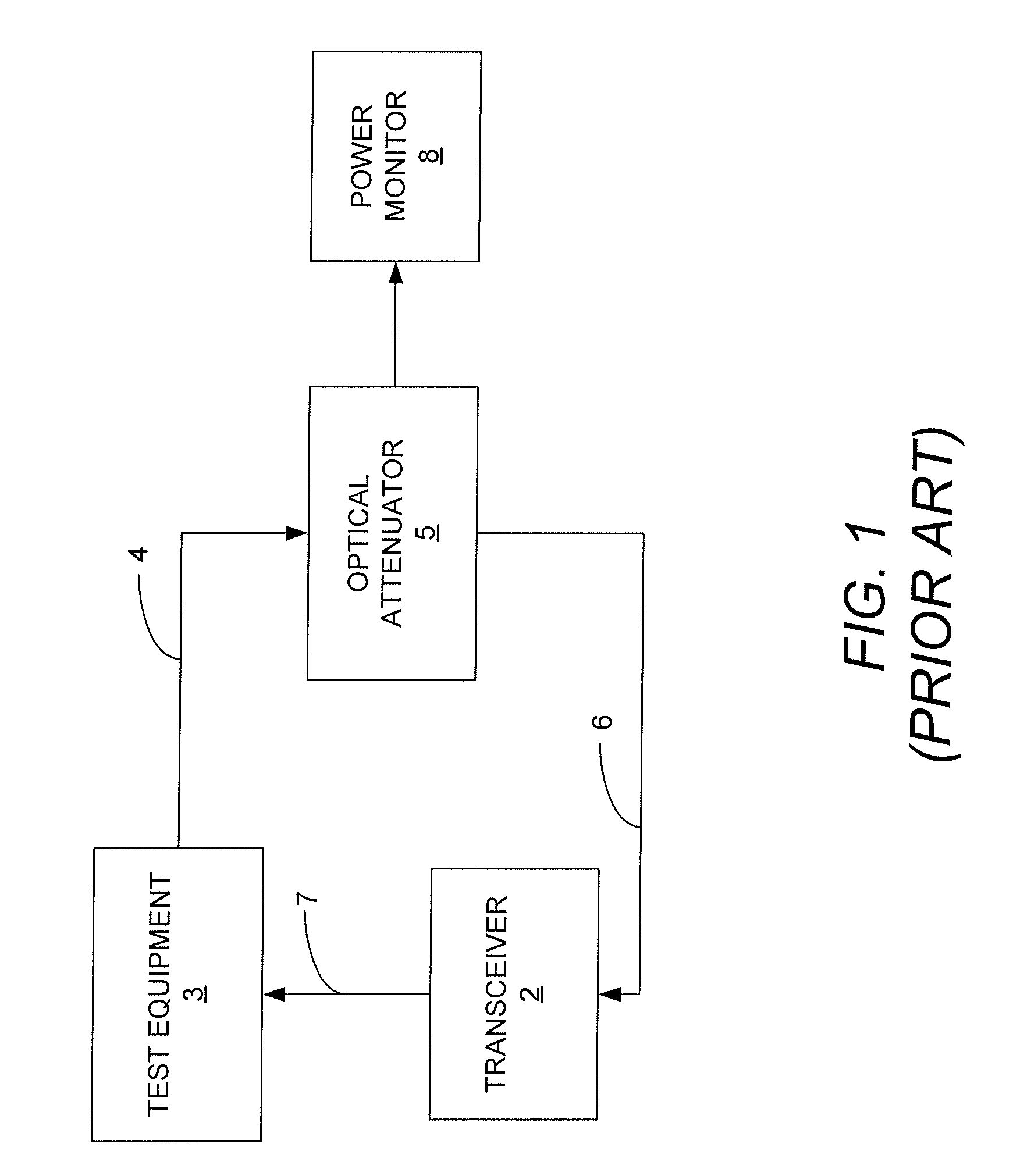
If the measured / extrapolated minimum receive power at the targeted BER remains at an acceptable level, the test passes; otherwise, the test fails.
One of the disadvantages of performing testing using a configuration such as that shown in FIG. 1 is that it is relatively difficult to setup and requires expensive test equipment.
Because of the difficulties and time associated with setting up the tests, each part cannot be individually tested.
Of course, it is possible, although unlikely, that one or more of the untested transceivers are faulty and would not have passed the tests, and thus there is a margin of error inherent in this approach.

Method used


Image

  • Method and apparatus for performing receiver sensitivity testing and stressed receive sensitivity testing in a transceiver
  • Method and apparatus for performing receiver sensitivity testing and stressed receive sensitivity testing in a transceiver
  • Method and apparatus for performing receiver sensitivity testing and stressed receive sensitivity testing in a transceiver

Examples


Embodiment Construction

[0014]In accordance with one embodiment, the apparatus is a transceiver that includes test circuitry that enables the transceiver to test itself to determine whether the receiver portion of the transceiver meets receiver sensitivity requirements and stressed receive sensitivity requirements. Thus, each and every transceiver is capable of being tested in a relatively short period of time without having to use expensive test equipment and without having to perform an extensive setup procedure in order to test the transceivers.

[0015]FIG. 2 illustrates a block diagram of the transceiver 10 in accordance with an embodiment having test circuitry that enables the transceiver to self-test receiver sensitivity and stressed receive sensitivity. The transceiver 10 has a transmitter portion 20 and a receiver portion 30. The transmitter and receiver portions 20 and 30 include self-test circuitry for measuring and evaluating receiver sensitivity and stressed receive sensitivity. The operations of...


PUM


Abstract

An apparatus and method are provided for use in a transceiver that enable the transceiver to test itself to determine whether the receiver portion of the transceiver meets receiver sensitivity requirements and stressed receive sensitivity requirements.

Description

TECHNICAL FIELD OF THE INVENTION[0001]The invention relates to transceivers used to transmit and receive data in the form of optical signals over optical waveguides. More particularly, the invention relates to a method and an apparatus for use in a transceiver to allow the transceiver to self-test receiver sensitivity and stressed receive sensitivity.BACKGROUND OF THE INVENTION[0002]In optical communications networks, transceivers are used to transmit and receive optical signals over optical fibers. On the transmit side of the transceiver, a laser of the transceiver generates amplitude modulated optical signals that represent data, which are then transmitted over an optical fiber coupled to a receiver. The received optical signals are converted into electrical signals by a photodiode and amplified to recover the data.[0003]Prior to a transceiver being shipped to a customer, various tests are performed to ensure that the transceiver operates properly. Two such tests are the receiver ...

Claims


Application Information

Patent Timeline
IPC IPC(8): H04B17/00
CPCH04B10/073
Inventor MILLER, FREDERICK W.
Owner AVAGO TECH WIRELESS IP SINGAPORE PTE
Learn More