
Visual recognition of user interface objects on computer

a technology of user interface and object recognition, applied in the field of visual recognition of objects, can solve the problems of not being able to recognize objects on computer screens or in computer applications, not being able to recognize objects on computer systems that are utilized, and being very slow

Inactive Publication Date: 2008-08-14
DETIEGE PATRICK J
View PDF5 Cites 24 Cited by
  • Summary
  • Abstract
  • Description
  • Claims
  • Application Information

AI Technical Summary

Benefits of technology

[0020]The foregoing and other objectives, features, and advantages of the present invention will become more readily appa...

Problems solved by technology

However, visual recognition of objects is not known to have been specialized to recognize objects appearing in the user interface of a computer system.
The main problem with conventional visual recognition of objects is that known computer systems do not recognize objects on a computer screen or in computer applications.
Another problem with conventional visual recognition of objects is that the computer systems that are utilized are very slow because they have a broad range of recognition capability and are thus too general.
Another problem with conventional visual recognition of objects is that the computer systems that are utilized are not accurate enough.
While known devices may be suitable for the particular purpose which they address, they are not suitable to recognize and localize objects on a computer screen such as input fields, buttons, icons, check boxes, text, and / or any other basic elements.
The main problem with conventional visual recognition of objects by known computer systems is that they do not recognize objects on a computer screen or in computer applications.
Also, as indicated above, other problems are that such computer-based object recognition systems are very slow because they are much too general and they are not accurate enough.

Method used


Image

  • Visual recognition of user interface objects on computer
  • Visual recognition of user interface objects on computer
  • Visual recognition of user interface objects on computer

Examples


Embodiment Construction

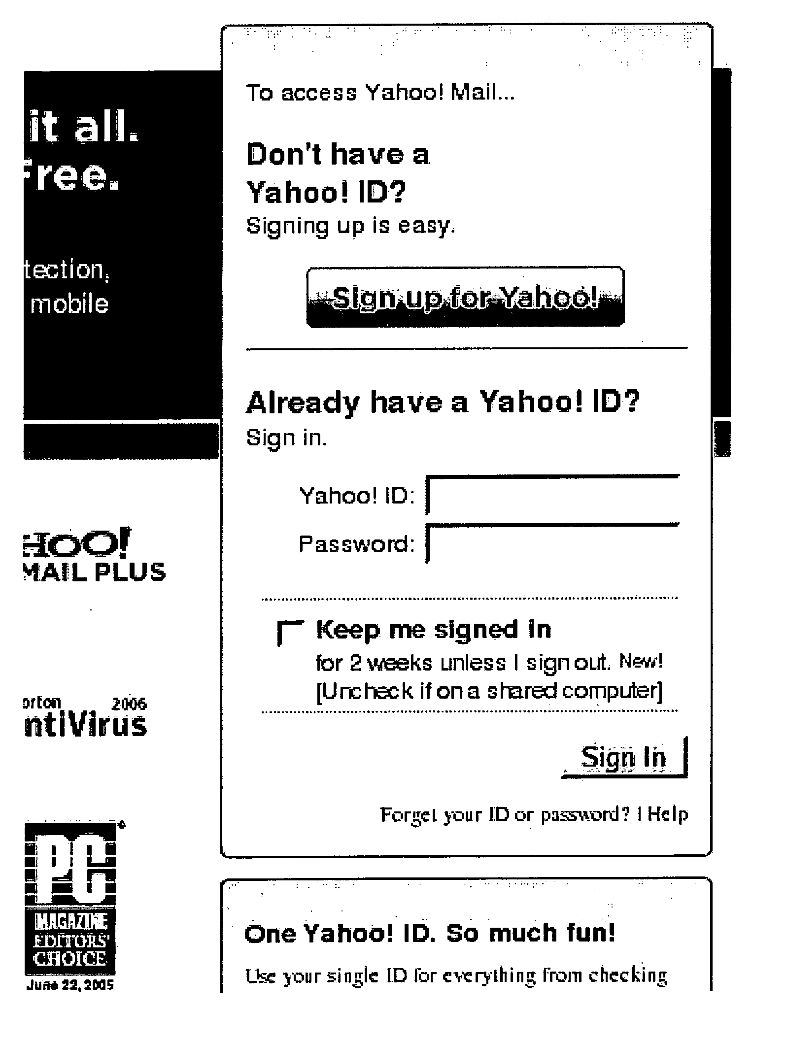
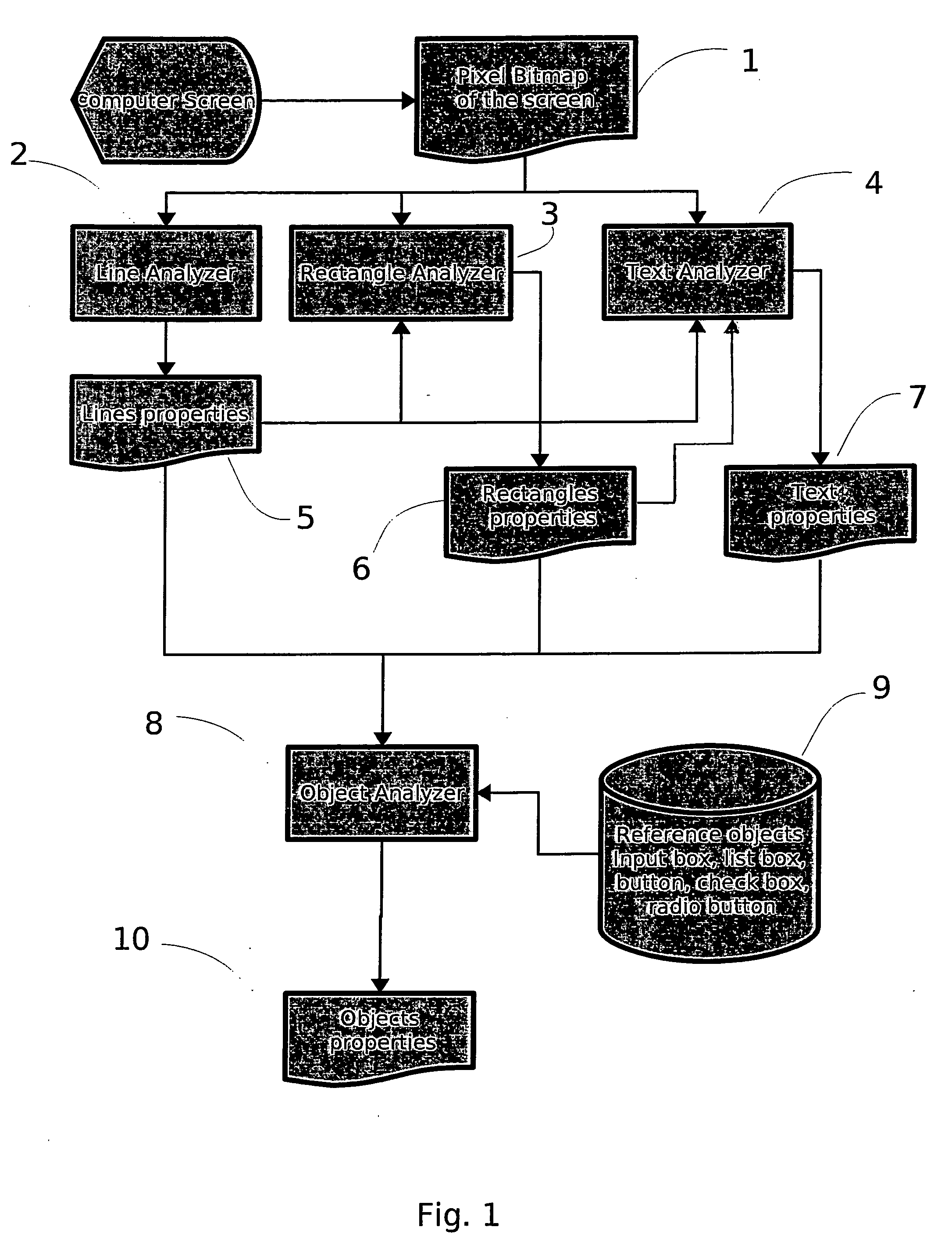
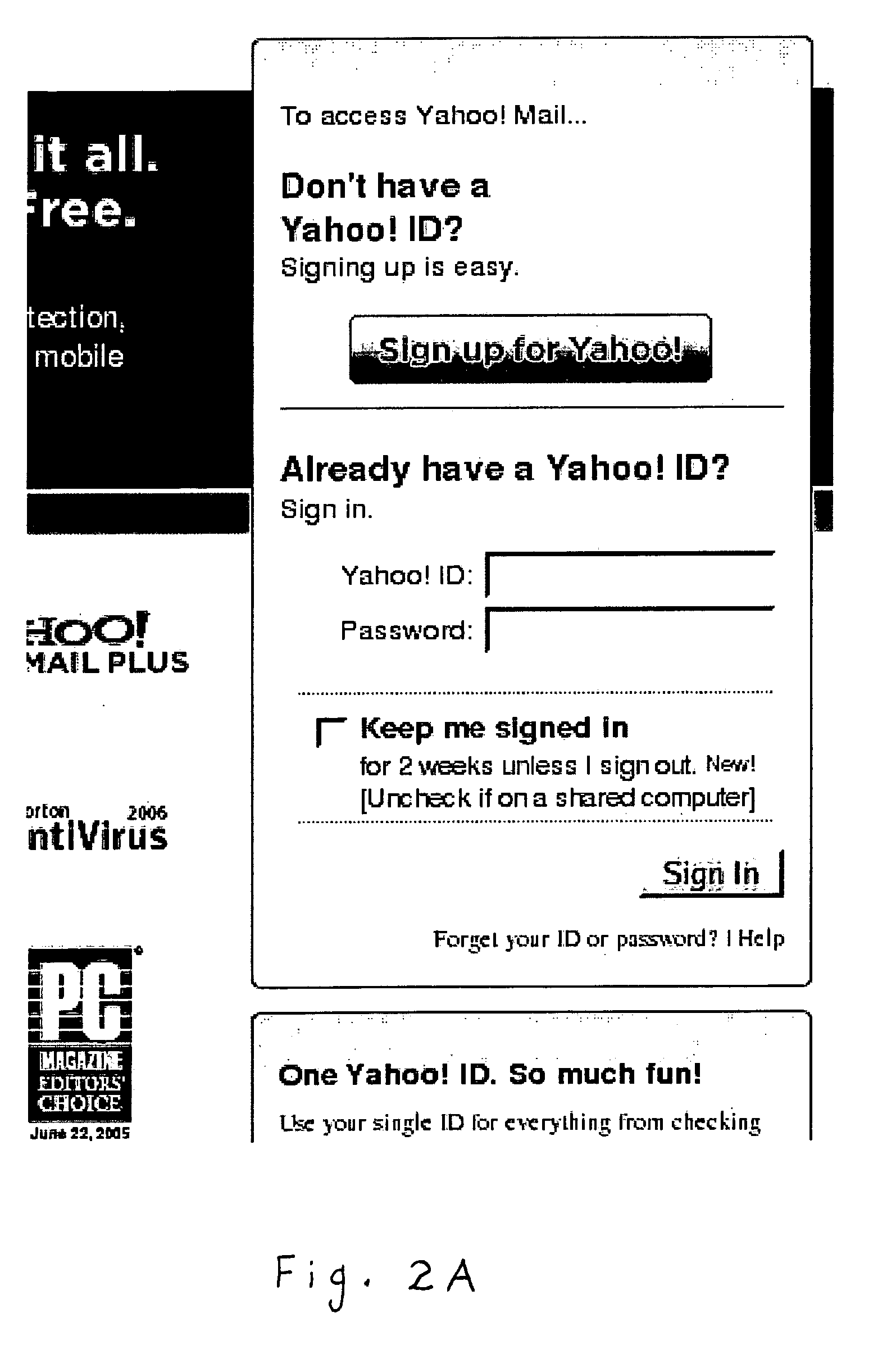
[0027]Turning now descriptively to the drawing figures, in which similar reference characters denote similar elements throughout the several views, the accompanying figures illustrate a visual recognition of user interface objects on computer, which comprises a system and method that capture the screen to an image, analyze the image, and create a layout with new virtual objects of the screen. A preferred embodiment of the system and method in accordance with the present invention capture the screen on a time basis like a movie camera to a bitmap format. From the bitmap, the system and method of the preferred embodiment generate a list of lines found on the screen, in which each line has properties such as length, color, starting point, angle, or other property. From the lines, the system and method of the preferred embodiment create rectangles found on the screen. From the bitmap, the system and method of the preferred embodiment also search each text element on the screen and conve...


PUM


Abstract

A visual recognition of user interface objects on computer to recognize and localize objects on a computer screen such as input fields, buttons, icons, check boxes, text, and / or any other basic elements. A system captures the screen to an image, analyzes the image, and creates a layout with new virtual objects of the screen. The system captures the screen on a time basis like a movie camera as a bitmap. From the bitmap, the system generates lists of lines found on the screen, in which each line has properties such as length, color, starting point, and angle, for example. From the lines, the system creates rectangles found on the screen. From the bitmap, the system also searches each text element on the screen, and converts each text element to Unicode text. From the bitmap, the lines, the rectangles, and the text found on the screen, the system creates virtual objects that represent a one-for-one correspondence with each object found on the screen.

Description

CROSS-REFERENCE TO RELATED PATENT APPLICATION[0001]This application relates to U.S. Provisional Patent Application No. 60 / 888,980, filed on Feb. 9, 2007, entitled VISUAL RECOGNITION OF USER INTERFACE OBJECTS ON COMPUTER, the disclosure of which is hereby incorporated in its entirety by this reference.BACKGROUND OF THE INVENTION[0002]1. Field of the Invention[0003]The present invention relates generally to visual recognition of objects and, more particularly, the present invention relates to visual recognition of user interface objects in a computer system. Specifically, various embodiments of the present invention provide an apparatus and method using a computer system to recognize and localize objects on a computer screen such as input fields, buttons, icons, check boxes, text, and / or any other basic elements.[0004]2. Description of the Prior Art[0005]It will be appreciated that visual recognition of objects has been in use for many years. Computer systems are known to be used with...

Claims


Application Information

Patent Timeline
IPC IPC(8): G06F3/048
CPCG06K9/00449G06V30/412
Inventor DETIEGE, PATRICK J.
Owner DETIEGE PATRICK J
Learn More