
Electrical power control outlet and system

a power control outlet and power control technology, applied in the direction of substation/switching arrangement details, substation/switching arrangement boards/panels/desks, substation/switching arrangement details, etc., can solve the problems of overloading the entire convention facility master power distribution system, affecting the use of electrical power by exhibitors, and leaving some exhibitors with insufficient electrical power supply, so as to prevent circuit breakage and prevent overloading of the master system. , the effect of preventing th

Active Publication Date: 2008-08-14
LAS VEGAS SANDS CORP
View PDF38 Cites 13 Cited by
  • Summary
  • Abstract
  • Description
  • Claims
  • Application Information

AI Technical Summary

Benefits of technology

"The invention is a device that regulates the amount of electricity given to exhibitors at trade shows and special events. It does this by isolating a specific outlet to a specific amperage of a shared circuit. If an individual outlet uses more electricity than the allotted amount, a fuse will break, suspending electricity flow to that outlet. The device includes a circuit box with fuses, a power cord, receptacles, an LED for indicating power availability, and a locking mechanism to prevent unauthorized access. The device prevents circuit breaks in the master power distribution system and ensures that exhibitors are only given limited, regulated quantities of electricity."

Problems solved by technology

One problem in this regard has been use by exhibitors of more electrical power than was purchased by the exhibitor(s).
Excess us of electrical power by one or more exhibitors then creates problems with the electrical distribution system itself, which problems are in addition to the problem of use of electrical power without payment to the provider.
These electrical system problems include the potential for overloading the entire convention facility master power distribution system, as well as leaving some of exhibitors with an insufficient supply of electrical power, depending of course on how the master power distribution system for the entire convention center is configured.
There is currently no known device or system that attempts to solve this problem, and there is no known device that limits the amount of electrical power that each individual outlet, group of outlets, power strip or group of power strips is allocated from the master power distribution system presently used in convention centers or facilities used for conventions.

Method used


Image

  • Electrical power control outlet and system
  • Electrical power control outlet and system
  • Electrical power control outlet and system

Examples


Embodiment Construction

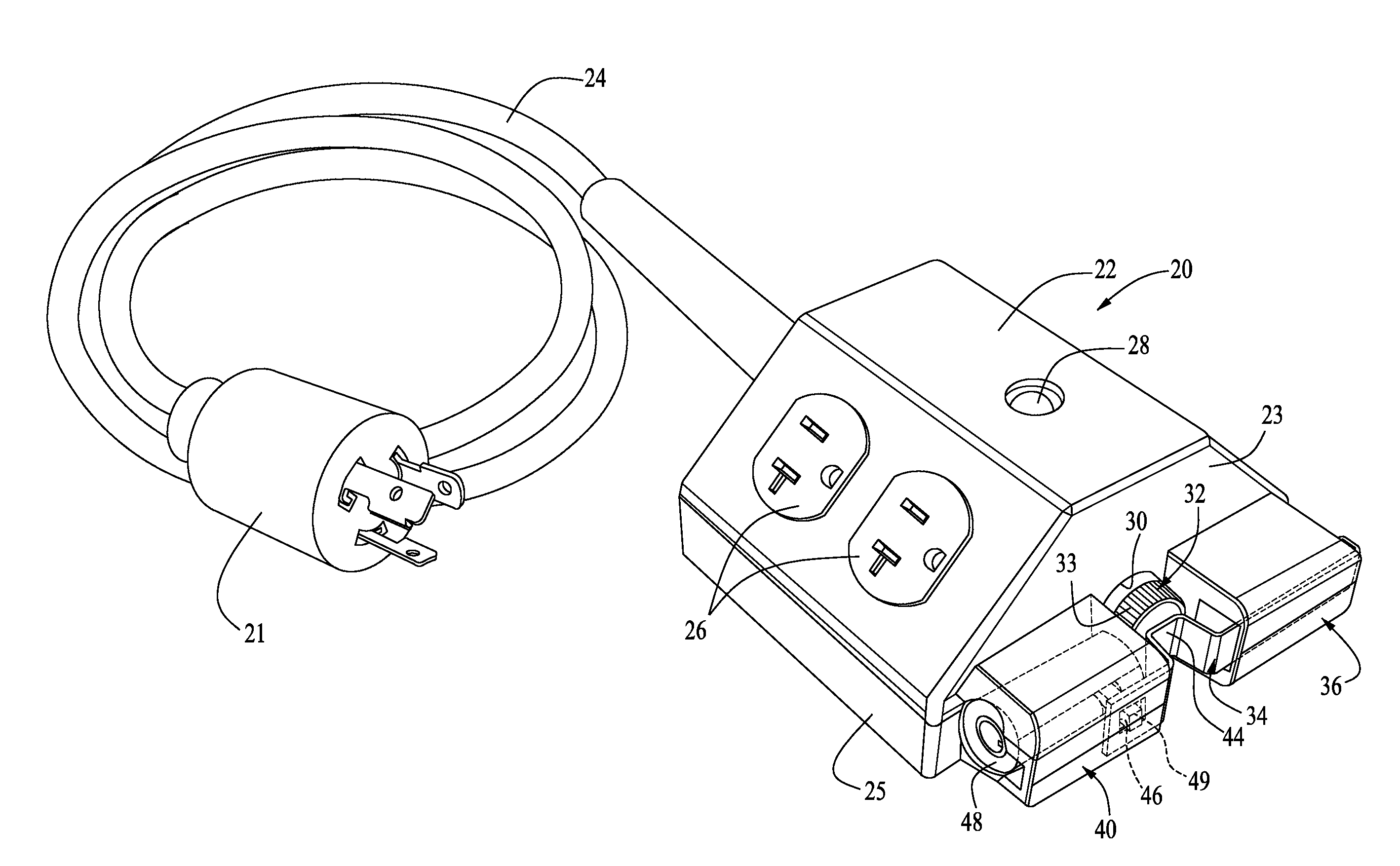
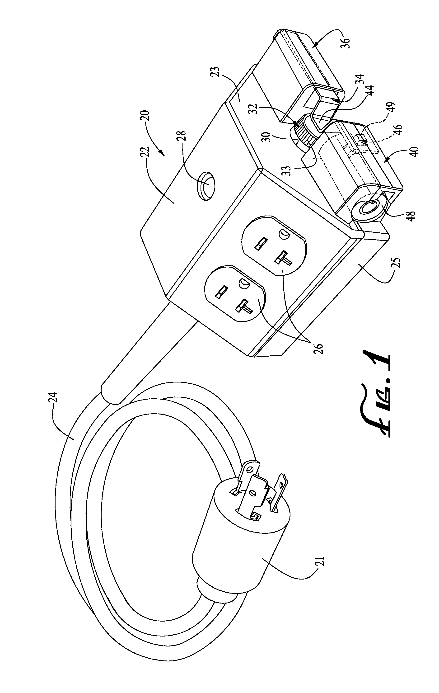
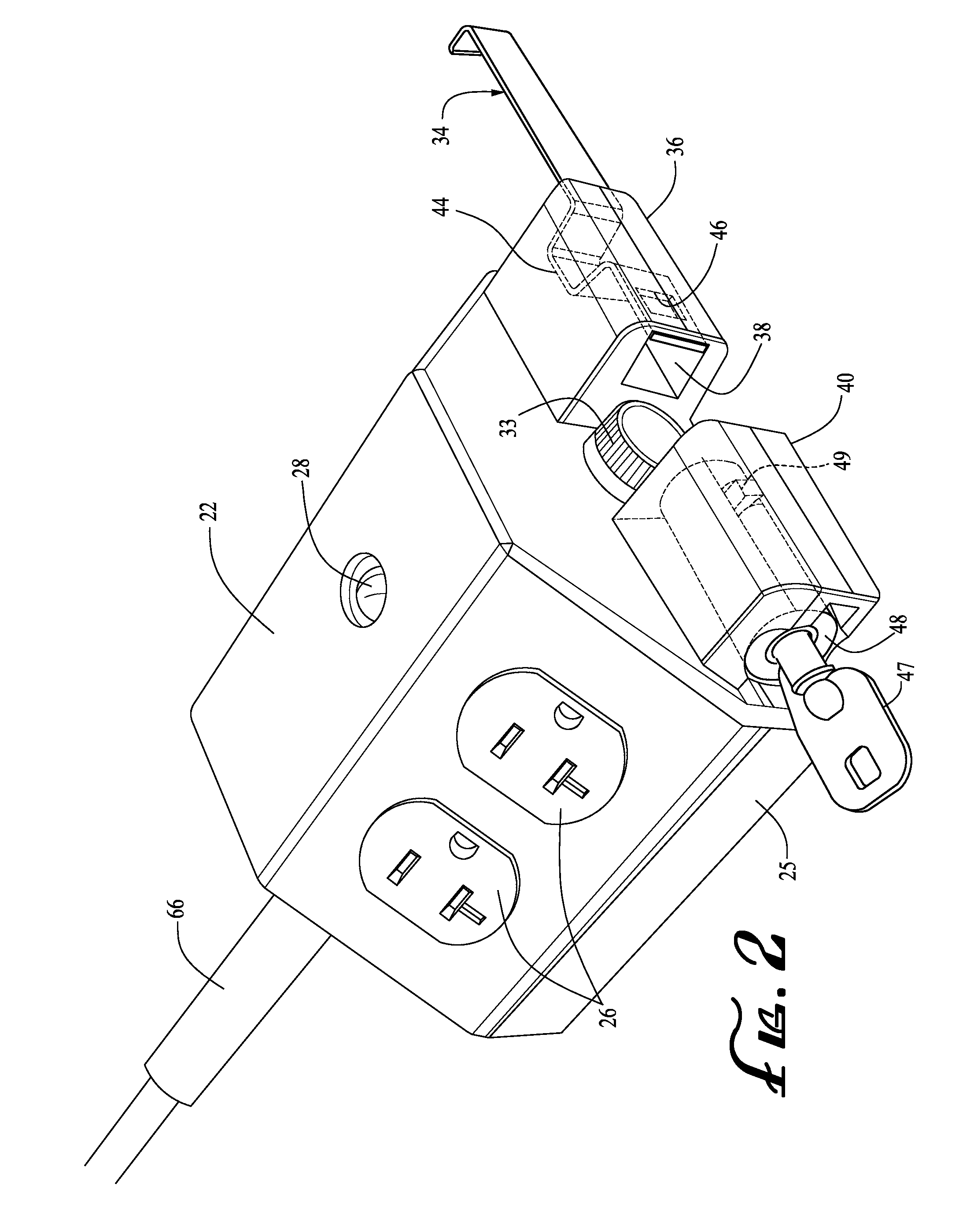
[0016]With reference to FIGS. 1 and 2 the exterior of a preferred embodiment of the present electrical power control circuit and locking device 20 will be described. The device 20 is a circuit box that preferably includes a housing 22, an electrical power cord 24, one or more power receptacles 26, such as an industrial grade, 20 ampere, nominal 115-125 VAC, NEMA 5-20 R configuration, duplex receptacle and a plug 21. The housing 22 is preferably of an electrical insulator material, such as a plastic that is durable. The presently most preferred material is a translucent polycarbonate that has been injection molded in the shape and configuration shown. Also, the housing is preferably of a 2-piece, molded construction, the pieces of which are preferably fastened together with a plurality of conventional fasteners, such as screws. In the embodiment shown in FIG. 1, the two pieces are screwed together with eight Philips type screws inserted into recesses provided in the backside or botto...


PUM


Abstract

Devices, systems and methods for regulating the distribution of electricity at events such as trade shows to prevent exhibitors from utilizing electricity not purchased from the convention center or other entity controlling electricity distribution, including lockable electric outlet boxes having a lockable fuse holder containing a fuse that restricts or limits a specific electrical outlet box or group of outlet boxes to a maximum electrical current or amperage.

Description

[0001]The present application claims priority on U.S. application 60 / 900,499, filed Feb. 9, 2007, entitled “Electrical Power Control Outlets, Methods of Use and Systems”, which is incorporated by reference herein.FIELD OF INVENTION[0002]The present power control outlet, method of use and system relates generally to devices and systems for regulating the distribution of electricity at events such as trade shows to prevent exhibitors from utilizing electricity not purchased from the convention center or other entity controlling electricity distribution. Specifically, the invention relates to lockable electric outlet devices and systems that restrict or limit a specific electrical outlet or group of outlets to a maximum electrical current or amperageBACKGROUND OF INVENTION[0003]At trade shows, exhibitors typically purchase electrical power or are allotted a certain amount of electrical power from a convention center provider and the convention center provider typically supplies electri...

Claims


Application Information

Patent Timeline
Patent Type & Authority Applications(United States)
IPC IPC(8): H01H85/20
CPCH01H85/24H01H85/32H01R25/003H01R13/68H01R13/6397
Inventor MATYAS, RAYMOND T.
Owner LAS VEGAS SANDS CORP
Learn More