
Business card sheet construction and methods of making and using same

a business card and construction technology, applied in the field of printing sheet construction, can solve the problems of inability to feed and print business cards, inability to use ink jet printers, laser printers, photocopiers and other ordinary printing and typing machines, cost and time-consuming separate cutting steps, etc., and achieve the effect of convenient removal and disposal

Inactive Publication Date: 2008-07-31
MCCARTHY BRIAN R +6
View PDF0 Cites 1 Cited by
  • Summary
  • Abstract
  • Description
  • Claims
  • Application Information

AI Technical Summary

Benefits of technology

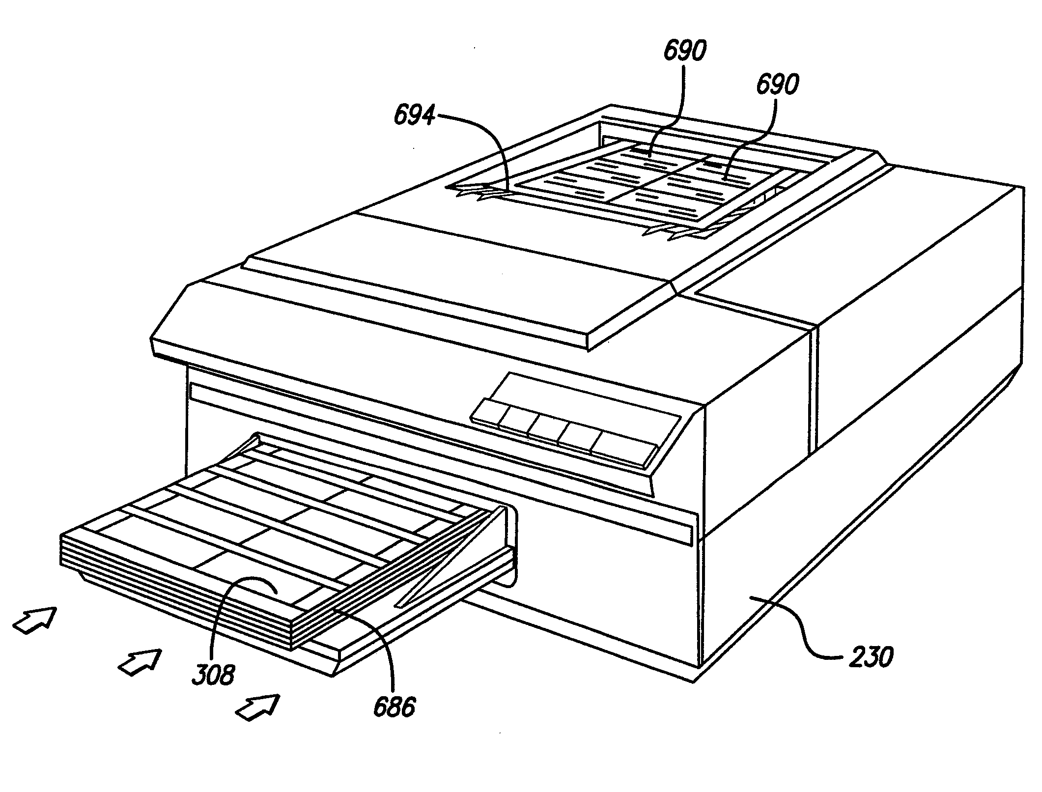
[0010]According to one embodiment of this invention, a web of laminate facestock is calendered along one or both edges thereof to assist in subsequent printer feed of the printable media sheets. The calendered edges help prevent the multiple sheet feed-through, misfeed and registration problems of the prior art. Lines are die cut through the laminate facestock and to but not through the liner sheet. These facestock cut lines define the perimeters of blank business cards (or other printable media) and a surrounding waste paper frame. These die cut lines do not cause sheets to get caught in one another. This allows sheets to be effectively fed into printers. Lines are then cut through the liner sheet, but not through the laminate facestock, to form liner sheet strips on the back face of the laminate facestock. The liner sheet cut lines can each be straight lines or they can be curving, wavy lines. The lines can be horizontally (or vertically) straight across the sheet or diagonally positioned thereon. According to one alternative, the lines can extend only part way across the sheet, such as from both side edges, to only a central zone of the sheet. Further steps in the process are to sheet the web into individual sheets, stack and package them and distribute the packaged sheets through retail channels to end users.
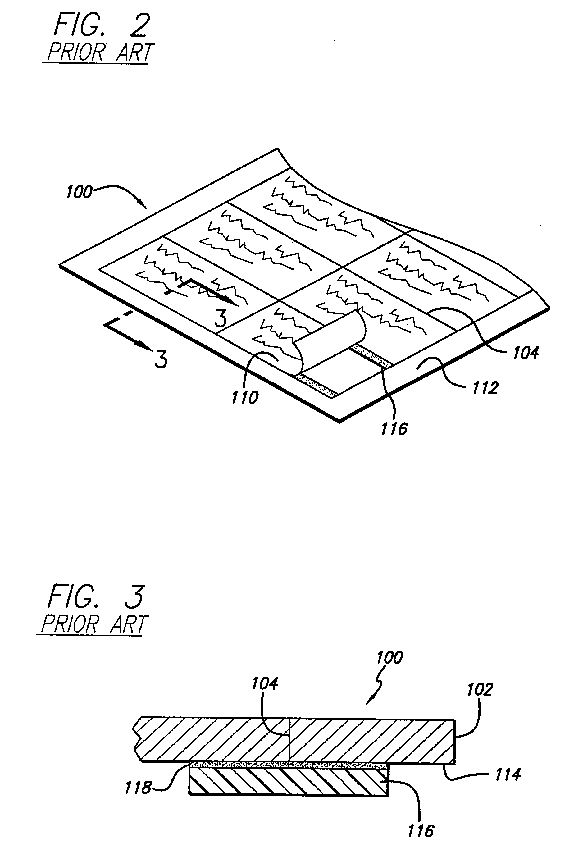
[0023]The ultraremovable adhesive is peeled off with the paper waste strips and the cover strips thereby providing a clean back side to the cardstock sheet (and thereby the printed media). The clean back side(s) (even when a coating thereon is provided) advantageously can be written on, that is, it accepts pencil, ink and even inkjet and laser printing. The ultraremovable adhesive sticks to the paper allowing for easy removal and disposal of the paper strips, and even though it is tacky it does not stick to anything permanently. In contrast, the “Paper Direct” product uses a removable adhesive. (Generally, adhesions of “ultraremovableTo assist the sheet in being fed into the printer or copier the lead-in edge thereof is preferably calendered, unlike the “Paper Direct” product. The web, before sheeting, is preferably calendered with textured calendering dies before the face cutting station. The calendering step is also preferably performed after the printing operation on the web wherein identifying and explanatory information is printed on the cardstock.” adhesives at their highest adhesion levels (to a surface such as stainless steel) are roughly half of what they are for conventional “removable” adhesive. A fundamental difference is that conventional adhesives provide complete contact with a substrate while ultraremovable adhesive provide partial contact;. This limited contact area is what prevents an ultraremovable adhesive from becoming permanent, over time).

Problems solved by technology

Small size media, such as business cards, ROLODEX rotary-type card file cards, party invitations and visitors cards, because of their small format, cannot be fed into and easily printed using today's ink jet printers, laser printers, photocopiers and other ordinary printing and typing machines.
However, this method is disadvantageous because the user must have access to such a cutting machine, and the separate cutting step is cost and time inefficient.
However, a problem with this product was that since these cards must be durable and professional looking, they had to be made from relatively thick and heavy paper.
And the thick, heavy perforated sheets are relatively inflexible, such that they cannot be fed from a stack of such sheets using automatic paper feeders into the printers and copiers.
However, a number of problems with this method prevented it from becoming generally commercially acceptable.
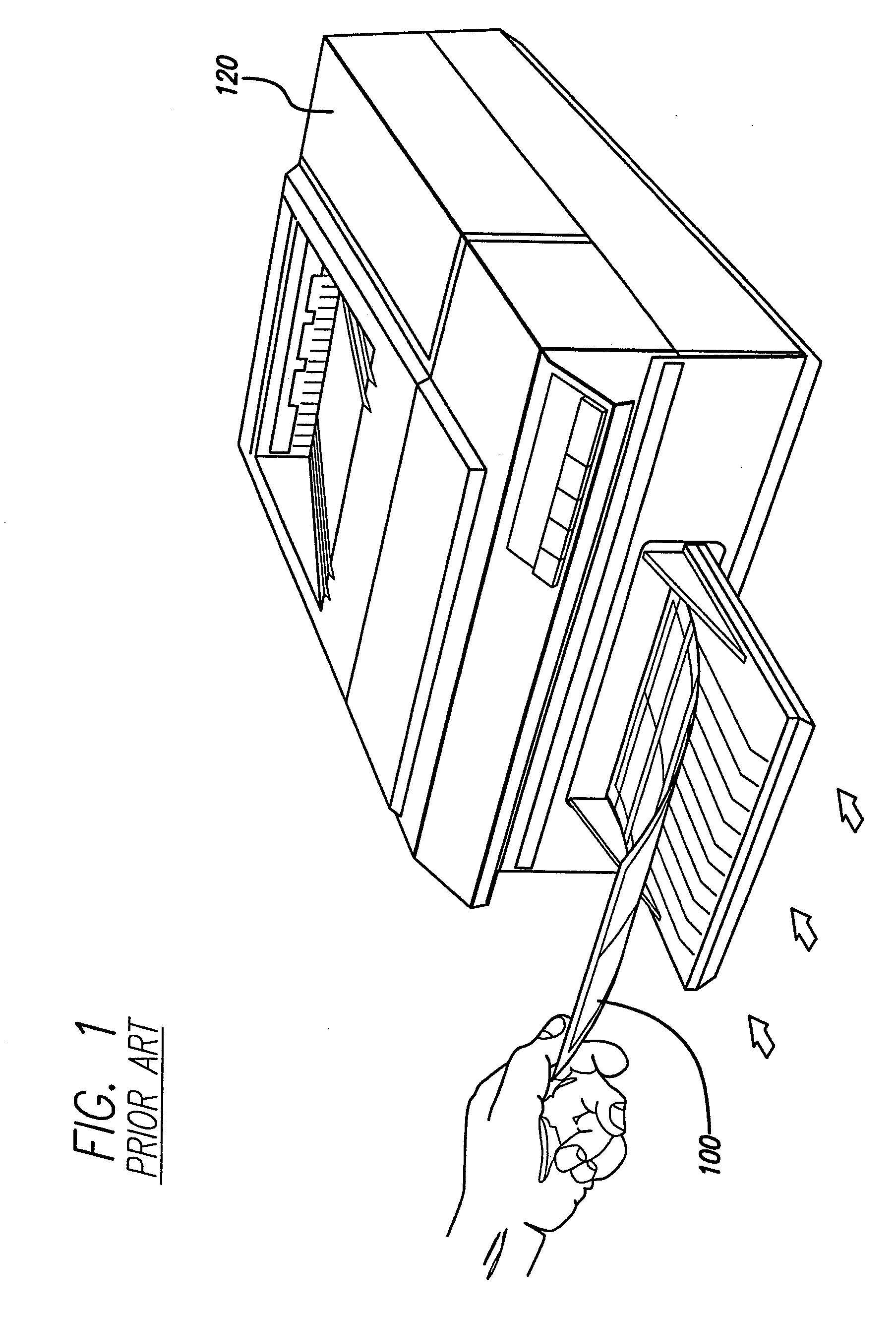
One of the problems with the prior art sheet product 100 is that printers have difficulty picking the sheets up, resulting in the sheets being misfed into the printers.
In other words, it is difficult for the infeed rollers to pull the sheets past the separation tabs within the printers.
Feeding difficulties are also caused by curl of the sheetstock 102 back onto itself .
Since the sheetstock 102 is a relatively stiff product, it is difficult for the infeed rollers of the printer 120 to handle this problem.
Another problem with the prior art sheet 100 is a start-of-sheet, off-registration problem.
This off-registration problem is often related to the misfeeding problem discussed in the paragraph above.
And this causes the print to begin at different places on the sheet, which is unacceptable to the users.

Method used


Image

  • Business card sheet construction and methods of making and using same
  • Business card sheet construction and methods of making and using same
  • Business card sheet construction and methods of making and using same

Examples


Embodiment Construction

[0073]A number of different embodiments and manufacturing processes of the dry laminated business card sheet constructions of this invention are illustrated in the drawings and described in detail herein. A representative or first sheet construction is illustrated generally at 200 in FIGS. 5, 6 and 7, for example.

[0074]Referring to FIG. 4, sheet construction 200 is formed by extrusion coating a low density polyethylene (LDPE) layer 204 onto a densified bleached kraft paper liner sheet (or base paper or base material) 208, which is not siliconized. The thin extrusion-cast LDPE layer 204 is unoriented. A suitable liner sheet 208 with layer 204 is available from Schoeller Technical Papers of Pulaski, N.Y. The extrusion-coated liner sheet is laminated to a facestock sheet (or card stock) 212 using a layer of hot melt pressure sensitive adhesive (PSA) 216. The facestock sheet 212, the adhesive layer 216 and the film 204 form a laminate facestock 220. The facestock sheet 212 can be curren...


PUM

PropertyMeasurementUnit
sizeaaaaaaaaaa
thicknessaaaaaaaaaa
thicknessaaaaaaaaaa

Abstract

Ultraremovable adhesive is applied to a paper sheet to form therewith a liner sheet, and the liner sheet is laminated to a cardstock sheet to form a laminate cardstock. The cardstock sheet is then die cut therethrough, but not through the liner sheet, to form cardstock cut lines that define at least in part perimeters of business cards (or other printable media). The outer face of the liner sheet is then die cut therethrough, but not through the cardstock sheet, to form liner sheet strips on a back side of the cardstock sheet. Some of the strips define cover strips covering some of the cardstock cut lines, and others of the strips define waste strips. The waste strips are then matrix removed from the back of the cardstock sheet. According to a preferred (dry laminate) embodiment the only liner sheet die cut is parallel to the leading edge of the sheet and forms a narrow leading edge liner strip which is removed. The resulting business card sheet construction is then fed through a printer or copier by the user and the desired indicia printed on the front sides of the business cards, while the cover strips hold the cards together as a unit sheet construction. After this printing operation, the printed cards are easily peeled off of the cover strips, ready for use. By designing the sheet construction to form the printed media with different sizes and shapes and by including optional scored fold lines, and / or additional flexibility cut lines or flexibility perforation lines, media aside from business cards, such as post cards and greeting cards, can be constructed.

Description

CROSS-REFERENCE TO RELATED APPLICATIONS[0001]This application claims the filing date benefit of provisional application Ser. No. 60 / 208,767, filed Jun. 2, 2000, and is a continuation-in-part of copending application Ser. No. 09 / 400,170, filed Sep. 21, 1999, which is a continuation-in-part of copending applications Ser. No. 09 / 158,728 filed Sep. 22, 1998 and Ser. No. 09 / 158,308 filed Sep. 22, 1998; the entire contents of all four of these applications and of International Publication WO 00 / 16978, published Mar. 30, 2000, are hereby incorporated by reference.BACKGROUND OF THE INVENTION[0002]The present invention relates to printable sheet constructions that are adapted to be fed into printers or copiers and indicia printed on different portions thereof and the portions thereafter separated into separate printed media, such as business cards. It further is concerned with methods for making those printing sheet constructions. Additionally, it relates to methods of using the sheet constr...

Claims


Application Information

Patent Timeline
Patent Type & Authority Applications(United States)
IPC IPC(8): B41M5/00B41J13/10B26D3/00B42D15/00B42D15/02
CPCB42D15/00B42D15/02B42P2241/22Y10T428/1495Y10T428/14Y10T156/108Y10T428/1486Y10T428/1476Y10T428/15Y10T156/1056Y10T156/1052Y10T428/2486Y10T428/149Y10T83/0605
Inventor MCCARTHY, BRIAN R.WEIRATHER, STEVEN CRAIGPATTERSON, CHARLES THURMONDSCROGGS, TONY LEEMOHAN, SUNJAY YEDEHALLICROSS, PATRICIA L.MOORE, ARTHUR B.
Owner MCCARTHY BRIAN R
Learn More