
Devices Based on Optical Waveguides with Adjustable Bragg Gratings

a technology of bragg grating and waveguide, which is applied in the direction of optical waveguide light guide, dual-mode fibre, instruments, etc., can solve the problem of cumbersome process of replacing wave guide segments

Inactive Publication Date: 2008-07-03
GENERAL PHOTONICS CORP
View PDF7 Cites 39 Cited by
  • Summary
  • Abstract
  • Description
  • Claims
  • Application Information

AI Technical Summary

Problems solved by technology

Replacing wave guide segments is a cumbersome process requiring that each end be properly coupled to the light source and the light receiving device.

Method used


Image

  • Devices Based on Optical Waveguides with Adjustable Bragg Gratings
  • Devices Based on Optical Waveguides with Adjustable Bragg Gratings
  • Devices Based on Optical Waveguides with Adjustable Bragg Gratings

Examples


Embodiment Construction

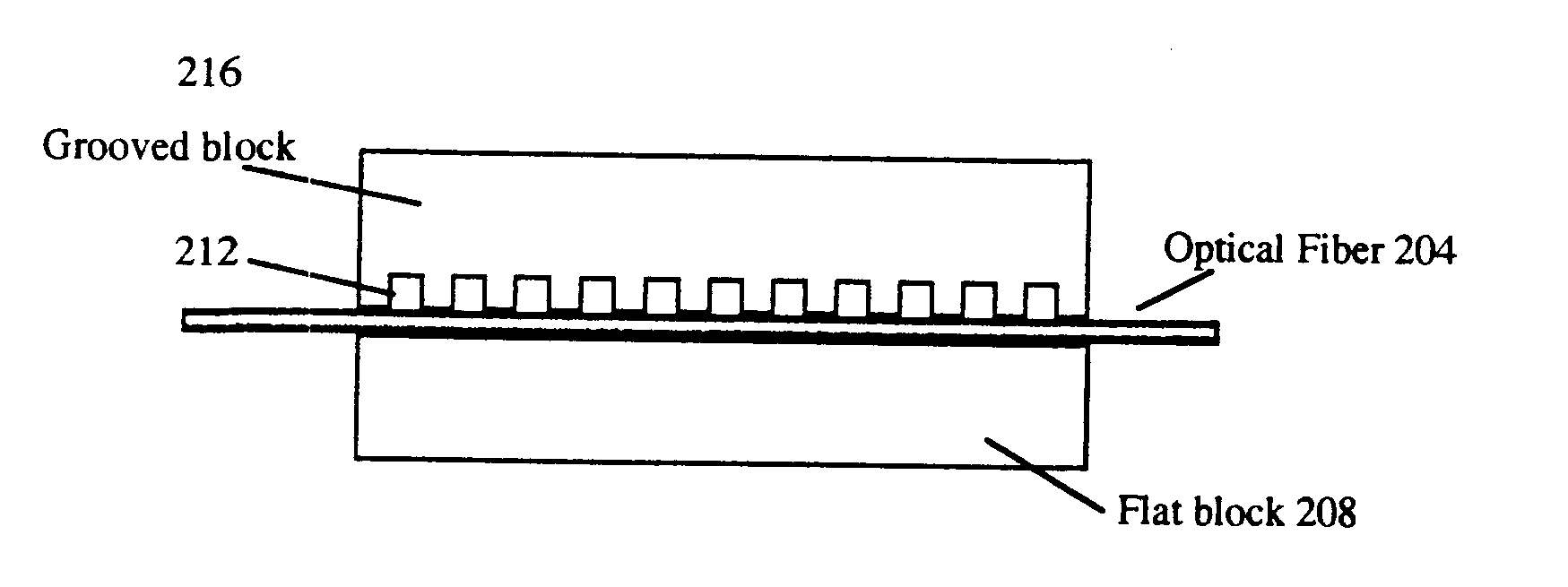
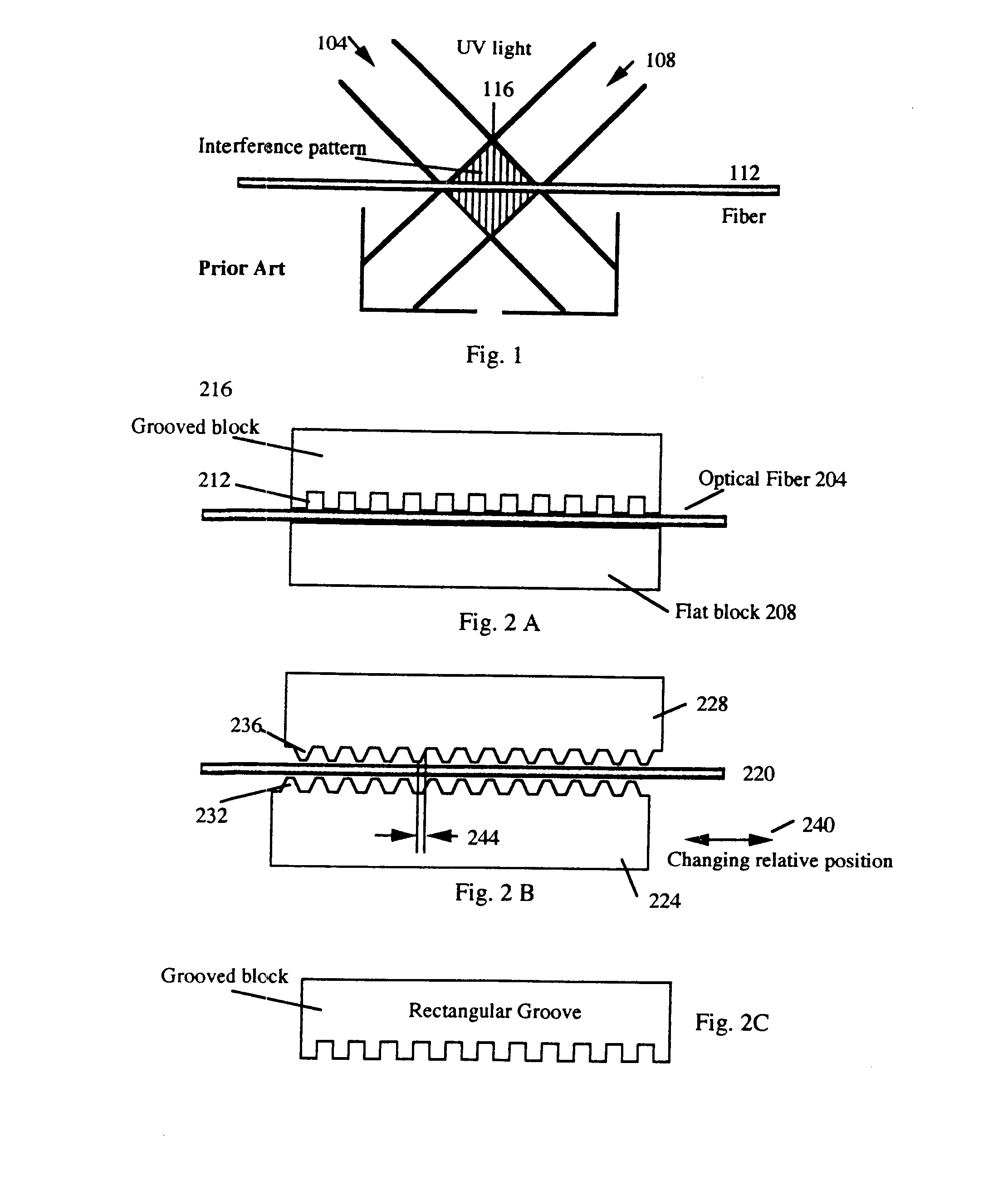
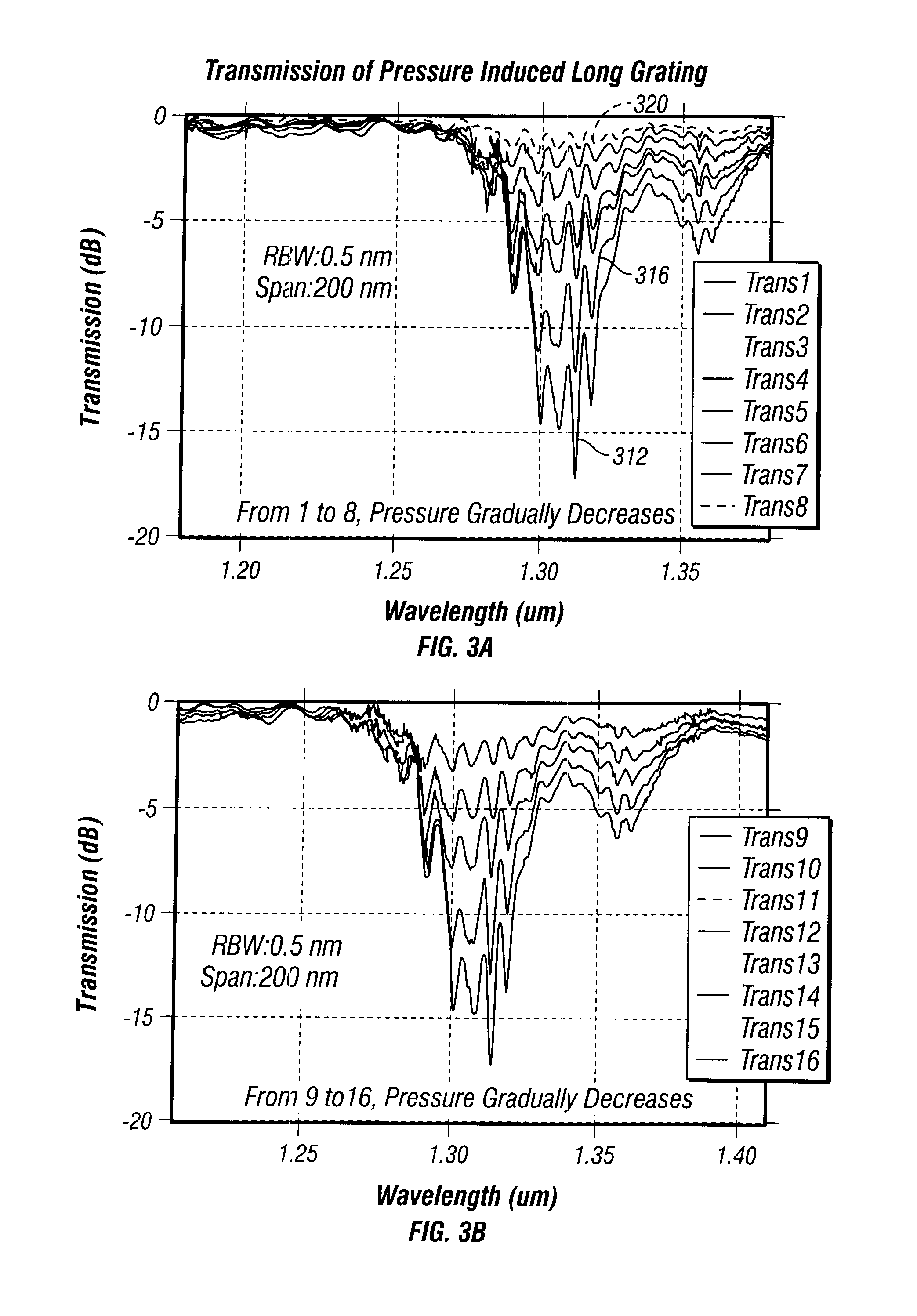
[0159]The following invention describes a method and apparatus of using an external grating to cause mode coupling in a wave guide. In the following invention, a number of terms will be used which are herein defined. A wave guide holder as used in this application is any device which holds a wave guide such that relative position, distance, or pressure between the waveguide and a periodic grating can be adjusted. In one embodiment, the waveguide holder holds the waveguide in a fixed position while the position of the external grating is adjusted. In an alternative embodiment, the waveguide holder is adjusted to move the waveguide to different positions with respect to the external grating. Examples of wave guide holders includes, but is not limited to, a block, a substrate of a semiconductor wave guide, the insulation surrounding a wave guide, or other apparatus which can be used to grip or prevent unwanted movement of the wave guide relative to a periodic grating. Furthermore, alth...


PUM


Abstract

A system for filtering light propagating in a waveguide is described. The system utilizes an adjustable periodic grating which induces mode coupling of predetermined frequencies of light propagating in the waveguide.

Description

[0001]This application is a continuation application and claims the benefit of priority under 35 USC 120 of co-pending U.S. application Ser. No. 10 / 946,665, filed Sep. 21, 2004, and issued as U.S. Pat. No. 7,233,720 on Jun. 19, 2007. The U.S. application Ser. No. 10 / 946,665 is a divisional of Ser. No. 10 / 649,179, filed Aug. 26, 2003 and issued as U.S. Pat. No. 6,795,616 on Sep. 21, 2004. The U.S. application Ser. No. 10 / 649,179 is a divisional (and claims the benefit of priority under 35 USC 120) of U.S. application Ser. No. 09 / 226,030, filed Jan. 6, 1999 and issued as U.S. Pat. No. 6,628,861 on Sep. 30, 2003. The disclosures of the prior applications are considered part of (and are incorporated by reference in) the disclosure of this application.BACKGROUND OF THE INVENTION[0002]1. Field of the Invention[0003]The present invention relates generally to controlling light propagating in a wave guide. More particularly, the present invention relates to using gratings to cause mode coupl...

Claims


Application Information

Patent Timeline
Patent Type & Authority Applications(United States)
IPC IPC(8): G02B6/26G02B6/34G02B6/02G02B6/28
CPCG02B6/02047G02B6/02061G02B6/02071G02B6/02195G02B6/266G02B6/29322G02B6/274G02B6/276G02B6/2861G02B6/2932G02B6/2706
Inventor YAO, XIAOTIAN STEVE
Owner GENERAL PHOTONICS CORP
Learn More