
Radio communication apparatus and radio communication method

Inactive Publication Date: 2008-07-03
NTT DOCOMO INC
View PDF21 Cites 13 Cited by
  • Summary
  • Abstract
  • Description
  • Claims
  • Application Information

AI Technical Summary

Benefits of technology

[0012]In view of the above-described problems, an object of the present invention is to provide a radio communication apparatus and a radio communication method that can achieve flexible and efficient use of the frequency bands, in a radio communication system configured to allocate either all frequency band available in the cell or specific frequency bands from among all the frequency bands available in the cell, as the frequency band available in each of the plurality of regions in the respective cells.
[0020]According to the present invention, it is possible to provide a radio communication apparatus and a radio communication method that can achieve flexible and efficient use of the frequency bands, in a radio communication system configured to allocate either all frequency band available in the cell or specific frequency bands from among all the frequency bands available in the cell, as the frequency band available in each of the plurality of regions in the respective cells.

Problems solved by technology

In other words, in the above-described conventional techniques, when a specific frequency band is previously allocated in a region, a subchannel in other than the specific frequency band cannot be used in the region regardless of a traffic state or the like.
Therefore, the frequency band cannot be used flexibly or efficiently.

Method used


Image

  • Radio communication apparatus and radio communication method
  • Radio communication apparatus and radio communication method
  • Radio communication apparatus and radio communication method

Examples


first embodiment

of the Present Invention

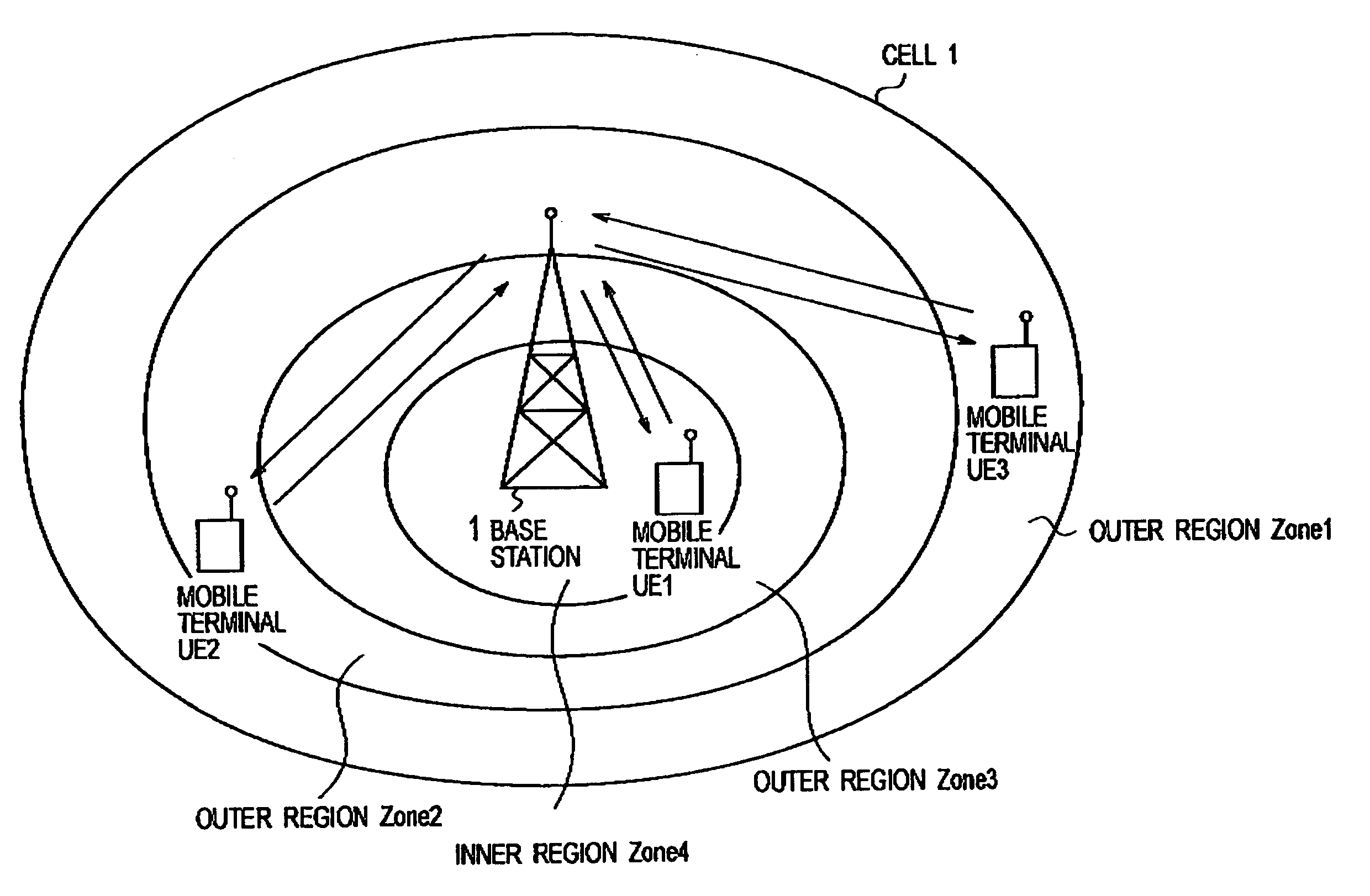
[0034]With reference to FIG. 4 to FIG. 10, a radio communication system according to the first embodiment of the present invention will be described.

[0035]The radio communication system according to a first embodiment of the present invention is a multi-user communication system using an orthogonal frequency division multiplexing (OFDM) method as a multiplexing method.

[0036]In the radio communication system according to this embodiment, part of a plurality of subcarriers included in a single communication path is allocated to a single mobile station (user), thereby an orthogonal frequency division multiple access (OFDMA) is achieved.

[0037]Such a radio communication system employing an OFDMA method is configured to transmit and receive data at high speed by using a subchannel having at least a single subcarrier.

[0038]Moreover, the radio communication system according to this embodiment is configured to divide each cell into a plurality of regions (for example,...

second embodiment

of the Present Invention

[0079]Hereinafter, a radio communication system according to a second embodiment will be described, mainly with respect to the differences between the radio communication systems according to this embodiment and the above-described first embodiment.

[0080]In the radio communication system according to this embodiment, a cell is configured to be divided into a plurality of regions Zone 1 to Zone 3 as shown in FIG. 11A.

[0081]In addition, in the example shown in FIG. 11A and FIG. 11B, a field 2 in a data frame corresponds to the region Zone 1, a field 4 in the data frame corresponds to the region Zone 2, and a field 3 in the data frame corresponds to the region Zone 3.

[0082]An allocation control unit 15 is configured to determine a region to which mobile terminals UE1 to UE4 should belong, from among the plurality of regions Zone 1 to Zone 3, in accordance with communication quality information received from each of the mobile terminals UE1 to UE 4 located in the...

third embodiment

of the Present Invention

[0089]Hereinafter, a radio communication system according to a third embodiment will be described, mainly with respect to the differences between the radio communication systems according to this embodiment and the above-described second embodiment.

[0090]In this embodiment, the allocation control unit 15 is configured to control a QoS class (quality of service class; communication quality class) of mobile terminals UE belonging to each of a plurality of regions Zone 1 to Zone 3.

[0091]In this embodiment, the QoS class includes “ErtPS (weighting coefficient: 5),”“UGS (weighting coefficient: 4),”“rtPS (weighting coefficient: 3),”“nrtPS (weighting coefficient: 2)” and “BE (weighting coefficient: 1).”

[0092]In the example shown in FIG. 12A, the QoS classes of the mobile terminals UE belonging to the region Zone 1 are “rtPS” or “UGS”, the QoS classes of the mobile terminals UE belonging to the region Zone 2 are “ErtPS” or “BE (best effort)”, and the QoS classes of t...


PUM


Abstract

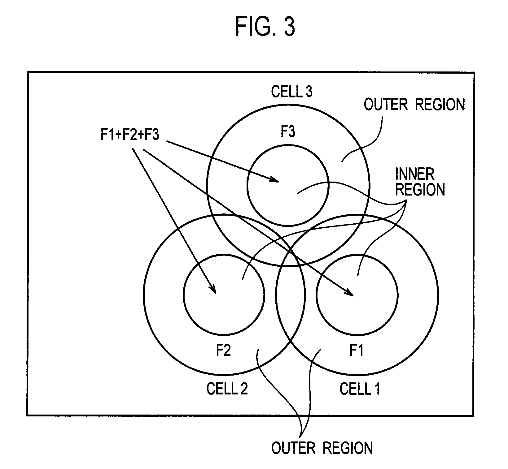
The present invention achieves a flexible and efficient use of frequency bands in a radio communication system in which all or part of frequency bands available in a cell is allocated respectively as frequency bands available in each of a plurality of regions in the cell. An allocation control unit included in a radio communication apparatus according to the present invention is configured to allocate all the frequency band f1 to f6 available in the cell, as a frequency band available in an inner region, to allocate specific frequency bands from among all the all the frequency band f1 to f6 available in the cell, as a frequency band available in an outer region, and to notify the specific frequency band available in the outer region in field B1 to B3 corresponding to the outer region in a data frame, by using a bit map pattern.

Description

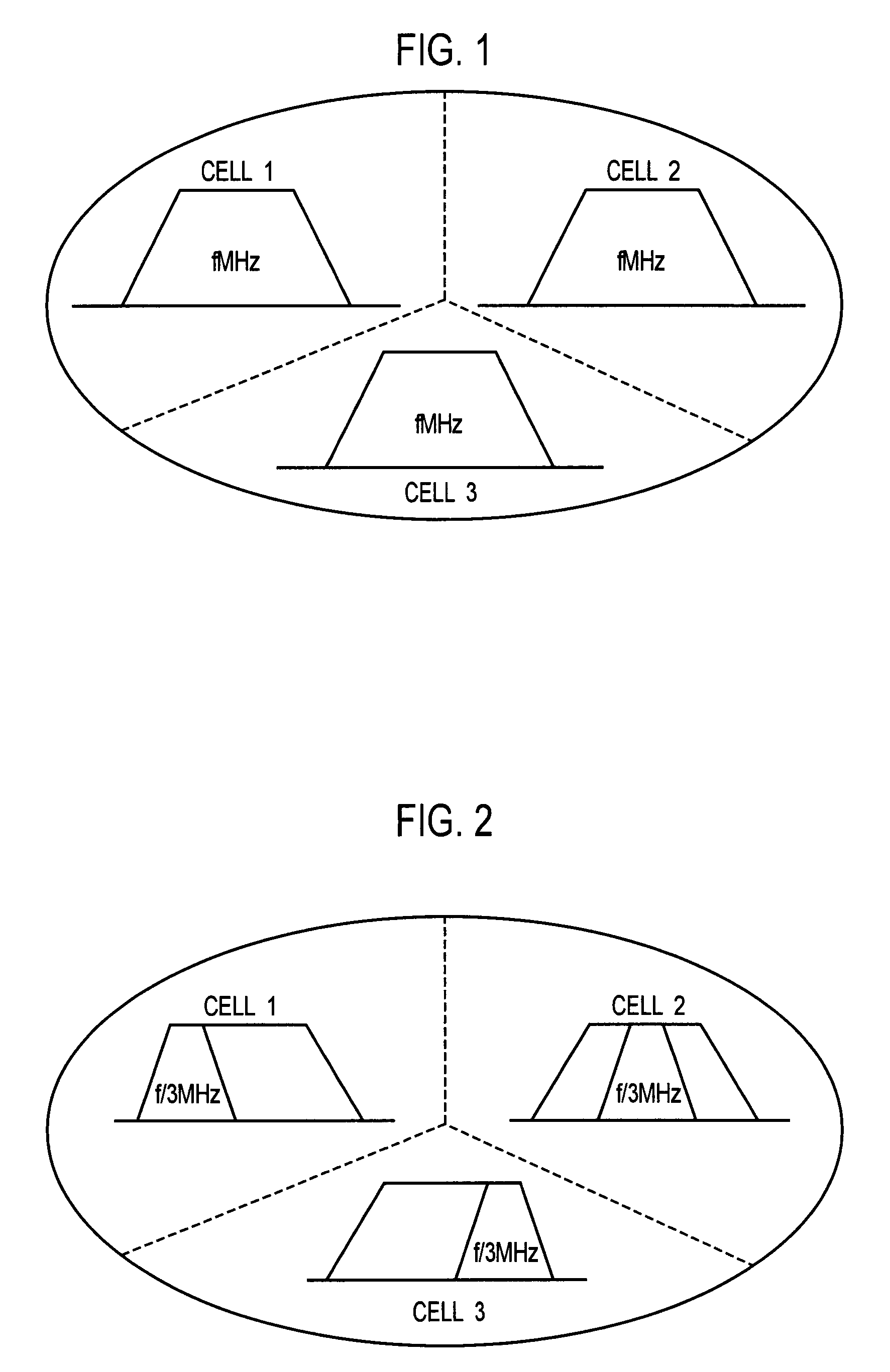
CROSS REFERENCE TO RELATED APPLICATIONS[0001]This application is based upon and claims the benefit of priority from prior Japanese Patent Applications No. 2006-344403 filed on Dec. 21, 2006, and 2007-291336 filed on Nov. 8, 2007; the entire contents of which are incorporated herein by reference.BACKGROUND OF THE INVENTION[0002]1. Field of the Invention[0003]The present invention relates to a radio communication apparatus and a radio communication method.[0004]2. Description of the Related Art[0005]A radio communication system using an FDMA (frequency division multiple access) method, such as an OFDMA (orthogonal frequency division multiple access) method or the like, has been conventionally known.[0006]In a case where there are three adjacent cells 1 to 3 in a radio communication system using the orthogonal frequency division multiple access method, the following two configurations have been known, for example. In the first configuration, the same frequency band (f MHz) is used in e...

Claims


Application Information

Patent Timeline
IPC IPC(8): H04Q7/00H04W16/10H04W16/30
CPCH04L5/0005H04L5/0037H04L5/006H04W72/082H04W16/10H04W16/30H04W72/0453H04L5/0062H04W72/541
Inventor TAKAHASHI, HIDEAKITAKEDA, SHINJIMIURA, SHUNJIASAKURA, HIROMITSU
Owner NTT DOCOMO INC
Learn More