
Drawer slide assembly

a slide assembly and drawer technology, applied in the field of drawer slide assembly, can solve the problems of not including other protective or locating mechanisms, increasing frictional resistance, preventing the drawer box from being smoothly and stably opened or closed, etc., to achieve smooth and stable opening and closing.

Inactive Publication Date: 2008-07-03
CHEN KUO CHEN
View PDF4 Cites 45 Cited by
  • Summary
  • Abstract
  • Description
  • Claims
  • Application Information

AI Technical Summary

Benefits of technology

[0004]A primary object of the present invention is to provide a drawer slide assembly that enables smooth and stable opening and closing of a drawer box.
[0005]Another object of the present invention is to provide a drawer slide assembly that provides a buffering effect.
[0007]With the sliding bearings so arranged, the drawer slide assembly provides a buffering effect and enables smooth and stable opening and closing of a drawer box.

Problems solved by technology

While the conventional drawer slides are provided with the rolling elements, they do not include other protective or locating mechanisms to cooperate with the rolling elements.
As a result, when the drawer box is not pulled or pushed by a force applied to a central position of the drawer box, the drawer box tends to sidewardly deviate from its sliding path, and the rolling elements tend to vibrate sidewardly and even separate from the slides to adversely increase the frictional resistance between the slides and the drawer box, preventing the drawer box from being smoothly and stably opened or closed.
And, while the rolling elements on the drawer slides enable smooth and effortless opening and closing of the drawer box, the drawer box easily slidable on the slides tends to produce a loud collision noise when it is carelessly closed with an overly large force.
In a worse condition, the drawer box and / or the rolling elements of the slides would become damaged due to collision when the drawer box is forcefully closed.

Method used


Image

  • Drawer slide assembly
  • Drawer slide assembly
  • Drawer slide assembly

Examples


Embodiment Construction

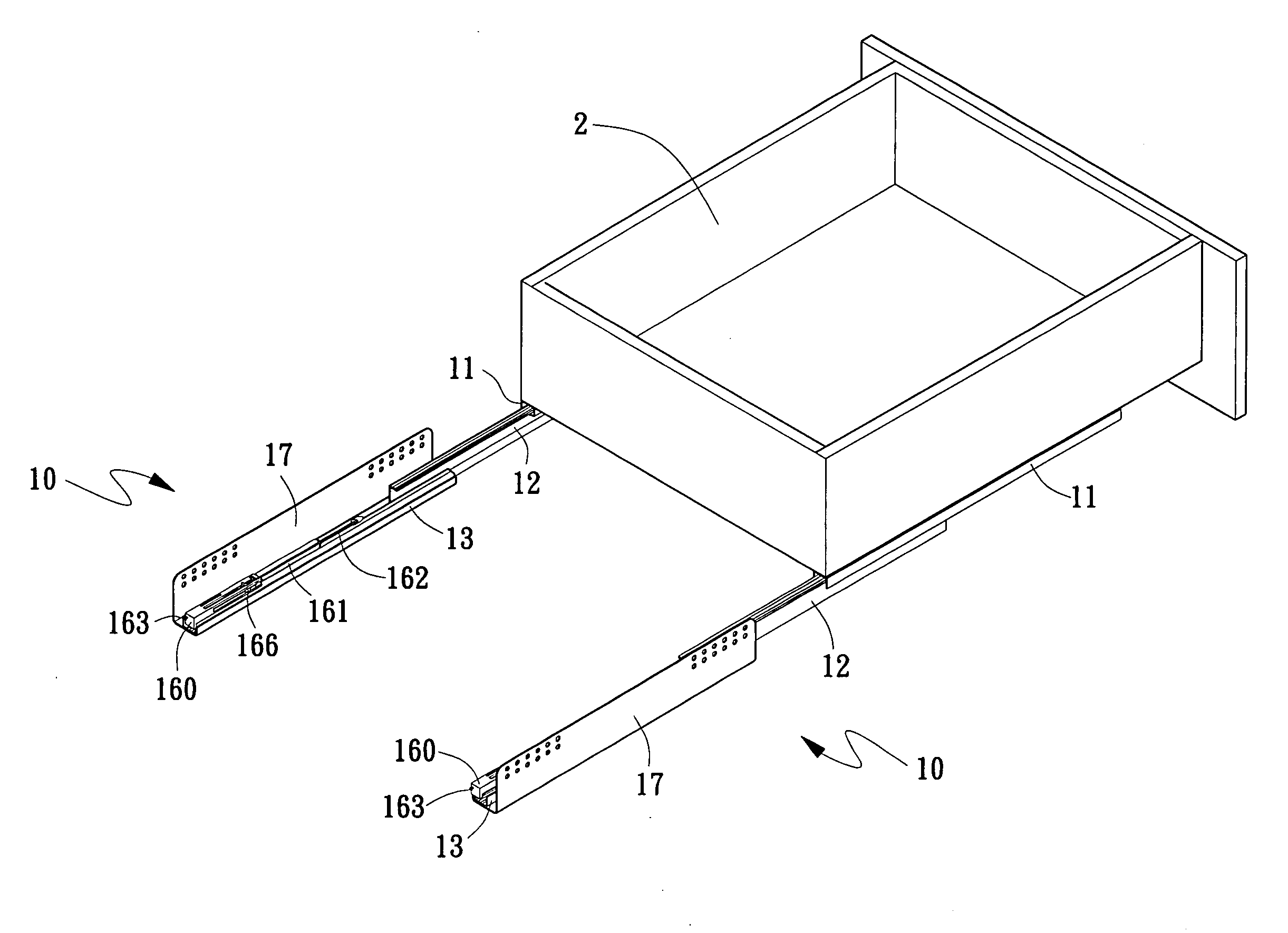
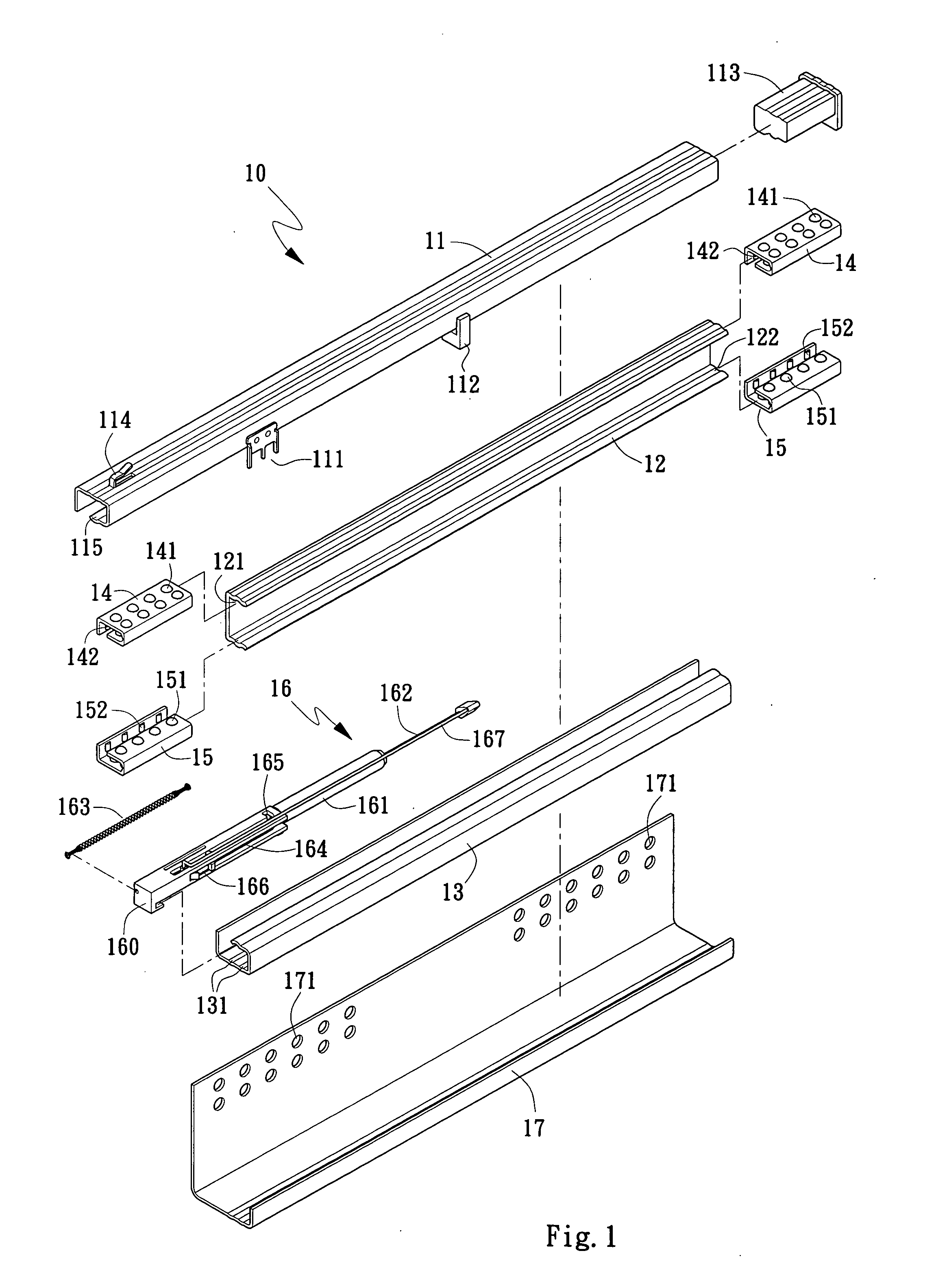
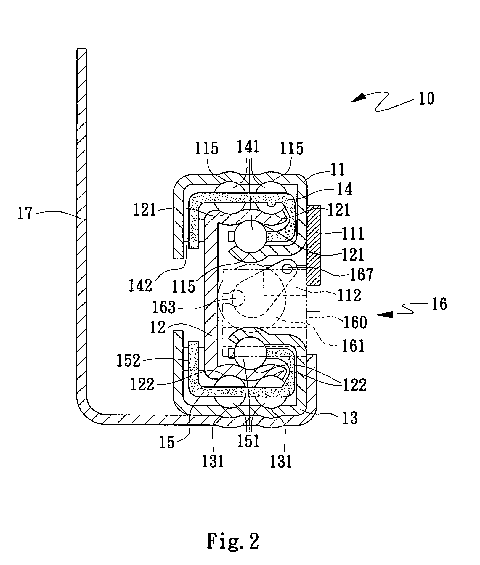
[0016]Please refer to FIG. 1 that is an exploded perspective view of a drawer slide assembly 10 according to an embodiment of the present invention, and to FIG. 2 that is an assembled sectional view of FIG. 1. As shown, the drawer slide assembly 10 of the present invention includes an upper slide 11; an inner slide 12 having a buffer unit 16 located therein; at least two upper sliding guides 14; and a mounting plate 17 provided with a plurality of mounting holes 171 for holding the assembled upper slide 11 and inner slide 12 to a fixed place.

[0017]The upper slide 11 has an outer end closed with a stopper 113, so as to prevent external dust from invading the upper slide 11 to adversely affect the smooth moving of the upper sliding guides 14 in the upper slide 11.

[0018]Each of the upper sliding guides 14 is provided on a top and a bottom with a plurality of first sliding bearings 141, such that the first sliding bearings 141 located at the top of the upper sliding guides 14 bear again...


PUM


Abstract

A drawer slide assembly includes an upper slide; an inner slide having a buffer unit located therein; at least two upper sliding guides being provided on top and bottom with first sliding bearings to bear against upper inner and lower inner surfaces of the upper slide and upper inner and upper outer surface of the inner slide, and on a lateral wall with second sliding bearings to bear against a lateral inner surface of the upper slide and a lateral upper outer surface of the inner slide, so that the upper slide and the inner slide are mutually slidably assembled to each other; and a mounting plate for holding the assembled upper slide and inner slide to a fixed place. With the sliding bearings so arranged, the drawer slide assembly provides a buffering effect to enable smooth and stable opening and closing of a drawer box.

Description

FIELD OF THE INVENTION[0001]The present invention relates to a drawer slide assembly, and more particularly to a drawer slide assembly that provides a buffering effect and enables smooth and stable opening and closing of a drawer box.BACKGROUND OF THE INVENTION[0002]Generally, a drawer box has two slides mounted to two lateral outer sides thereof. The two slides are provided with a plurality of rolling elements each, so as to reduce the frictional resistance between the drawer box and the slides, allowing the drawer box to be smoothly and effortlessly opened or closed. While the conventional drawer slides are provided with the rolling elements, they do not include other protective or locating mechanisms to cooperate with the rolling elements. As a result, when the drawer box is not pulled or pushed by a force applied to a central position of the drawer box, the drawer box tends to sidewardly deviate from its sliding path, and the rolling elements tend to vibrate sidewardly and even ...

Claims


Application Information

Patent Timeline
IPC IPC(8): A47B88/04
CPCA47B88/0481A47B88/47
Inventor CHEN, KUO-CHEN
Owner CHEN KUO CHEN
Learn More