
Connector and a connector assembly

Inactive Publication Date: 2008-06-26
SUMITOMO WIRING SYST LTD
View PDF8 Cites 15 Cited by
  • Summary
  • Abstract
  • Description
  • Claims
  • Application Information

AI Technical Summary

Benefits of technology

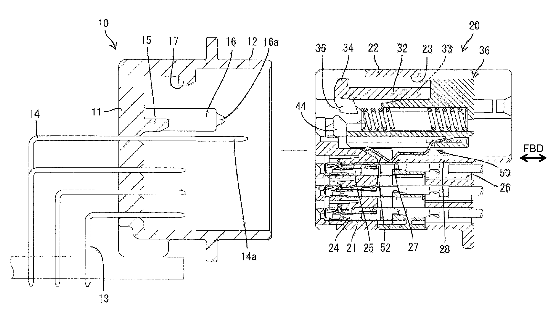
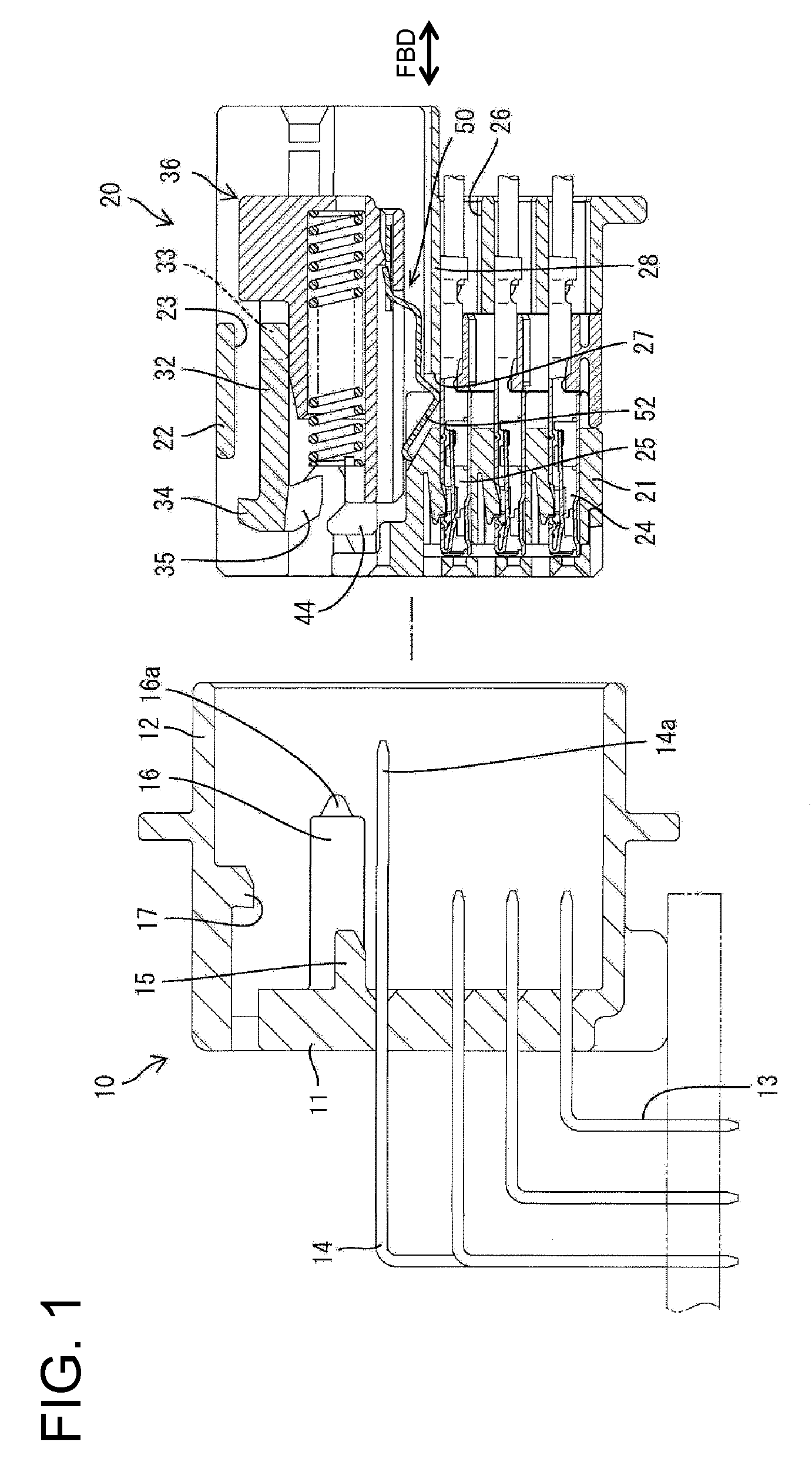
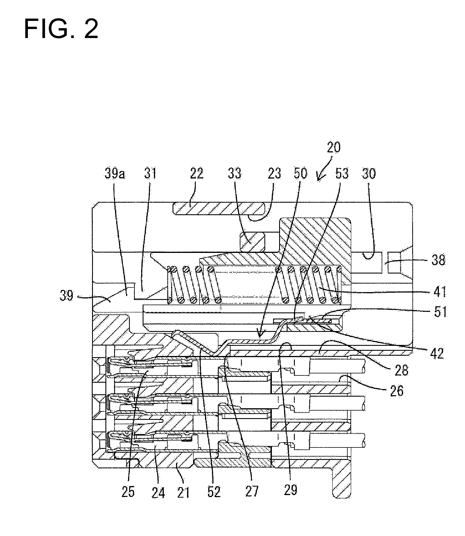
[0019]On the contrary, the movable member of the subject invention is held at the malfunction preventing position and the terminal fittings are shorted by the shorting terminal so that the malfunction preventing state is held until the two housings are connected properly. The movable member is moved to the connection detecting position when the two housings are connected properly. As a result, the shorting terminal shorts the detection terminals to set a connection detecting state and, simultaneously, the shorted state (malfunction preventing state) of the terminal fittings by the shorting terminal is released. Accordingly, when the shorted state for the malfunction prevention is released, the two housings already are connected properly and the circuit between the two housings already is closed. Therefore, there is no likelihood of malfunction.
[0023]The shorting terminal and the two terminal fittings are partitioned by the partition wall with the two housings properly connected and the movable member moved to the connection detecting position. Therefore the shorted state of the terminal fittings by the shorting terminal can be released reliably.

Problems solved by technology

The shorting terminal for preventing the malfunction of the airbag and the shorting terminal for detecting the connected state of the housings are provided separately in the above-described connector, thereby increasing the number of parts and the cost.

Method used


Image

  • Connector and a connector assembly
  • Connector and a connector assembly
  • Connector and a connector assembly

Examples


Embodiment Construction

[0042]A connector in accordance with the invention includes male and female housings that are identified respectively by the numerals 10 and 20 in FIGS. 1 to 17. The housings 10, 20 are connectable with and separable from each other. Connecting ends of the housings are referred to as the front.

[0043]The male housing 10 is made e.g. of synthetic resin and includes a terminal holding wall 11 and a rectangular tubular receptacle 12 that projects forward from the outer peripheral edge of the terminal holding wall 11. L-shaped male terminal fittings 13 and L-shaped left and right detection terminals 14 penetrate the terminal holding wall 11. Front sections of the male terminal fittings 13 and front sections of the detection terminals 14 are accommodated in the receptacle 12. Left and right releasing pieces 15 project forward at positions adjacent to and above the detection terminals 14 on the front surface of the terminal holding wall 11 and at the back end of the receptacle 12. A pressi...


PUM


Abstract

A movable member (36) is located at a malfunction preventing position and a pair of functional terminals (25) are shorted by a shorting terminal (50) unless two housings (10, 20) are properly connected, whereas the movable member (36) is moved to a connection detecting position and the shorting terminal (50) shorts a pair of detection terminals (14) at the same time as being disengaged from the pair of functional terminals (25) when the two housings (10, 20) are properly connected. Since the shorting terminal (50) is commonly used to short the pair of functional terminals (25) for the malfunction prevention and the like and to short the pair of detection terminals (14) for the detection of a connected state of the two housings (10, 20), the number of parts can be reduced.

Description

BACKGROUND OF THE INVENTION[0001]1. Field of the Invention[0002]The invention relates to a connector and to a connector assembly.[0003]2. Description of the Related Art[0004]Japanese Patent No. 3284200 discloses a connector for an airbag circuit of an automotive vehicle. The connector has a first shorting terminal in an airbag side housing for shorting two terminal fittings of an airbag circuit to prevent a malfunction of the airbag when the two housings of the connector are separated for maintenance or other reason. Further, two detection terminals are provided in the power-supply side housing for confirming the connection of the two housings, and a second shorting terminal is provided in the airbag side housing for shorting the detection terminals when the two housings are connected properly.[0005]The shorting terminal for preventing the malfunction of the airbag and the shorting terminal for detecting the connected state of the housings are provided separately in the above-descri...

Claims


Application Information

Patent Timeline
IPC IPC(8): H01R13/64
CPCH01R13/6272H01R2201/26H01R13/7032H01R13/641
Inventor KOBAYASHI, YUTAKANAKAMURA, KEIICHINORO, YUTAKAKIKUCHI, TAKAHIROISHIKAWA, YOSHIYUKI
Owner SUMITOMO WIRING SYST LTD
Learn More