
Device For Validating Valuable Parpers

Active Publication Date: 2008-06-05
JAPAN CASH MASCH CO LTD
View PDF8 Cites 10 Cited by
  • Summary
  • Abstract
  • Description
  • Claims
  • Application Information

AI Technical Summary

Benefits of technology

[0013]The present invention can provide an inexpensive, lightweight and small-sized device capable of smoothly validating valuable papers during rotation of the paper while preventing unauthorized extraction of the paper.

Problems solved by technology

However, such an anti-pull back device is disadvantageous because it has to be separately assembled and then mounted in the bill validating device in addition to conveyer device 72, thereby leading to increase in number of involved parts, rise in cost for manufacture and heavier unit of the device as well as longer passageway of bill and larger size of the device.
This undesirably extends the examination time of bill 80, and also there is a risk that a user may accidentally pull out bill 80 returned to inlet 78 before resending bill 80 inward.
By the way, the devices shown in Japanese Patent Disclosure No. 9-190559 and Japanese Patent Disclosure No. 11-31250 unfavorably require a longer bill passageway for transporting bill and increased number of involved parts because they must transport a bill along linear bill passageway by means of convey belts and incorporate additional anti-pull back device on the way of bill passageway which requires separate validation and anti-pull back areas.
In particular, when rotation of a conveyer motor is converted into linear motion by means of conveyer belts, the devices undesirably incur energy conversion loss from electric to kinetic energy.
Elongation of conveyer belts in contact to bill tends to at least partly reduce the grasping force of bill so as to cause jamming of bill on the way of transportation, fail transportation or hinder smooth transportation of bill.
Unlike these, bill validating device shown in U.S. Pat. No. 5,495,929 cannot prevent unauthorized extraction of bill from inside of the device since it has a simplified bill passageway without anti-pull back device.

Method used


Image

  • Device For Validating Valuable Parpers
  • Device For Validating Valuable Parpers
  • Device For Validating Valuable Parpers

Examples


Embodiment Construction

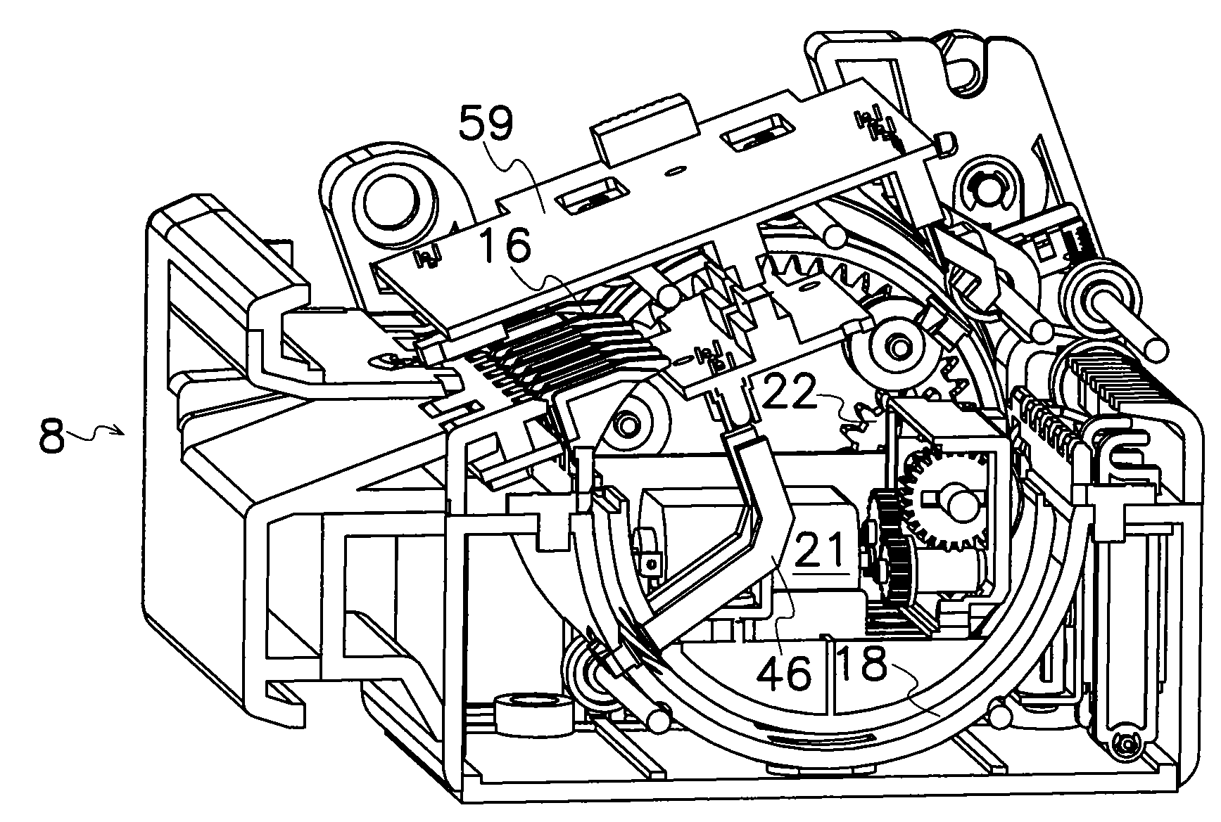
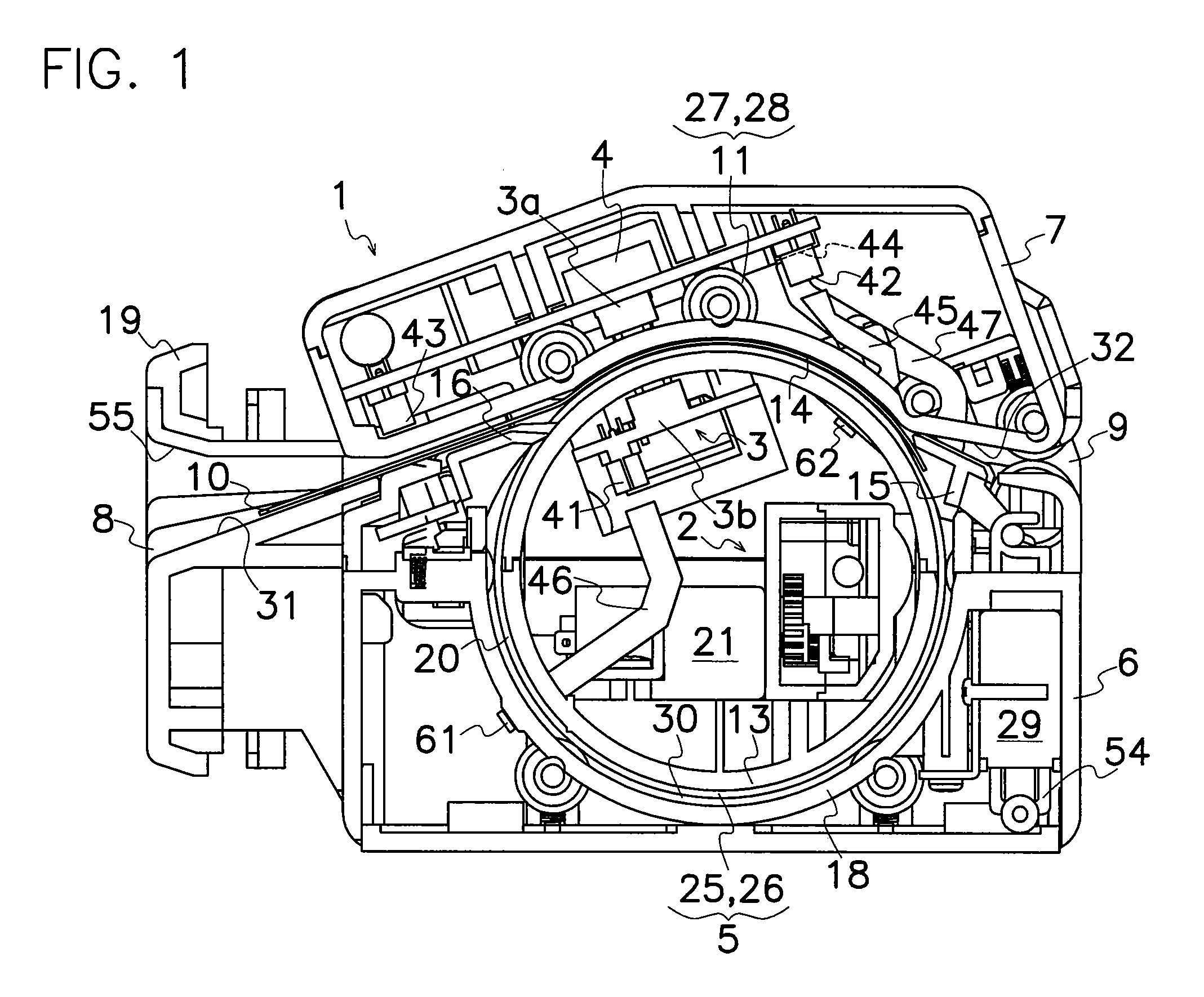
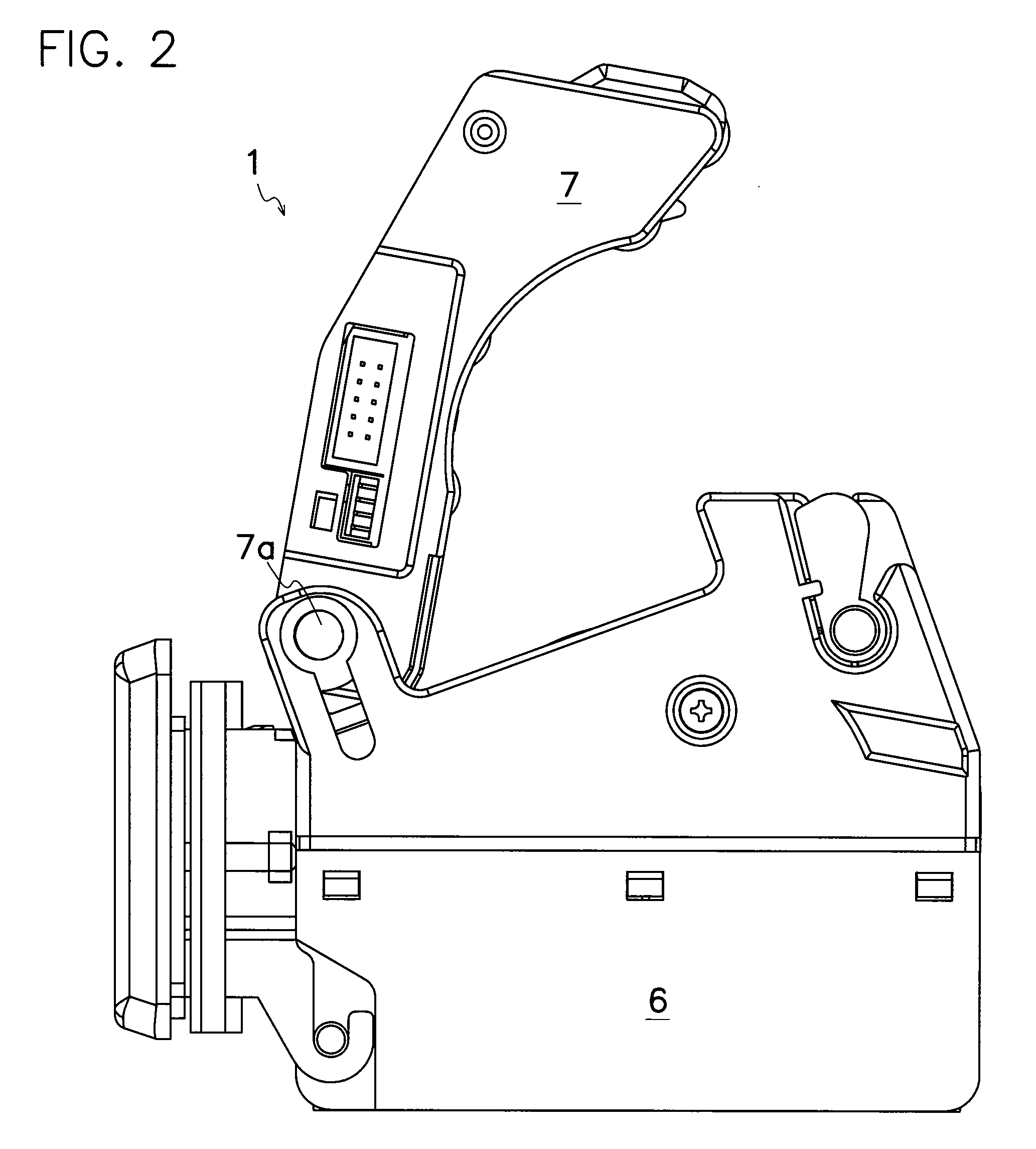
[0040]The following is description with respect to FIGS. 1 to 24 on embodiments of the device for validating valuable papers according to the present invention applied to a bill validating device.

[0041]As shown in FIG. 1, the bill validating device according to the present invention, comprises a casing 1 having an inlet 8 and an outlet 9, a conveying device 2 for transporting a bill 10 inserted into inlet 8 to outlet 9, a validator sensor 3 for detecting physical features of bill 10 carried by conveying device 2 to produce detection signals, and a control device 4 for validating bill 10 based on or in view of detection signals from sensor 3 to control operation of conveying device 2. Casing 1 may be formed of synthetic resin or engineering plastics such as polyacetal (POM), acrylonitrile butadiene styrene (ABS), polyamide (PA) or polycarbonate (PC) resin, and, as shown in FIG. 2, comprises a lower shell 6 and an upper shell 7 rotatably attached to lower shell 6 around a shaft 7a. Al...


PUM


Abstract

A conveying device 2 in a device for validating valuable papers, comprises a rotor arrangement 5 rotatably mounted in a casing 1, a drive device 12 for rotating rotor arrangement 5, and a roller arrangement 11 disposed around and in contact to an outer circumferential surface of rotor arrangement 5. A bill 10 inserted from an inlet 8 of casing 1 is grasped between rotor arrangement 5 and roller arrangement 11 to wind up the whole length of bill 10 around rotating rotor arrangement 5 so that bill 10 can reliably be transported with rotation of conveying device 2 while preventing slippage of bill 10 on rotor arrangement 5. Also, bill 10 can be rotated together with rotor arrangement 5 one revolution or more to positively prevent unauthorized extraction of bill 10 by means of any extraction tool. When a sensor 3 detects physical property of bill 10 and a control device 4 considers bill 10 to be genuine in view of the detected physical property of bill 10, the device separates bill 10 from rotor arrangements 5 to discharge it through an outlet 9.

Description

BACKGROUND OF THE INVENTION[0001]This invention relates to a device for validating valuable papers, in particular, of the type capable of discriminating authenticity of bills with high accuracy and also preventing unauthorized extraction of a bill out of the device.[0002]As shown in FIGS. 25 and 26, a typical prior art bill validating device comprises a casement 71 having an inlet 78 and an outlet 79, a conveyer device 72 for transporting a bill 80 inserted from inlet 78 to outlet 79, a sensor 73 for detecting a physical property such as an optical or magnetic feature of bill 80 transported by conveyer device 72 to produce a detection signal, and a control device 74 for determining whether bill 80 is genuine or not in view of detection signal from sensor 73 to control operation of convey device 72. Casement 71 comprises a lower shell 76 and an upper shell 77 rotatably attached to lower shell 76. Conveyer device 72 comprises a motor 91, a drive gear 92 mounted on an output shaft of m...

Claims


Application Information

Patent Timeline
IPC IPC(8): G07F7/04
CPCG07D7/04G07D11/0036G07D7/12G07D11/22
Inventor UEMIZO, YOSHIAKIOKAWA, KATSUTOSHITAKEHARA, HISASHI
Owner JAPAN CASH MASCH CO LTD
Learn More