
Adjustable occipital plate

a technology of occipital plate and adjustable plate, which is applied in the direction of ligaments, prostheses, osteosynthesis devices, etc., can solve the problems of increasing surgical time, needing to maintain separate inventory, and high assembly cost, and achieves efficient and secure multi-adjustability

Active Publication Date: 2008-05-29
ZIMMER BIOMET SPINE INC
View PDF99 Cites 83 Cited by
  • Summary
  • Abstract
  • Description
  • Claims
  • Application Information

AI Technical Summary

Benefits of technology

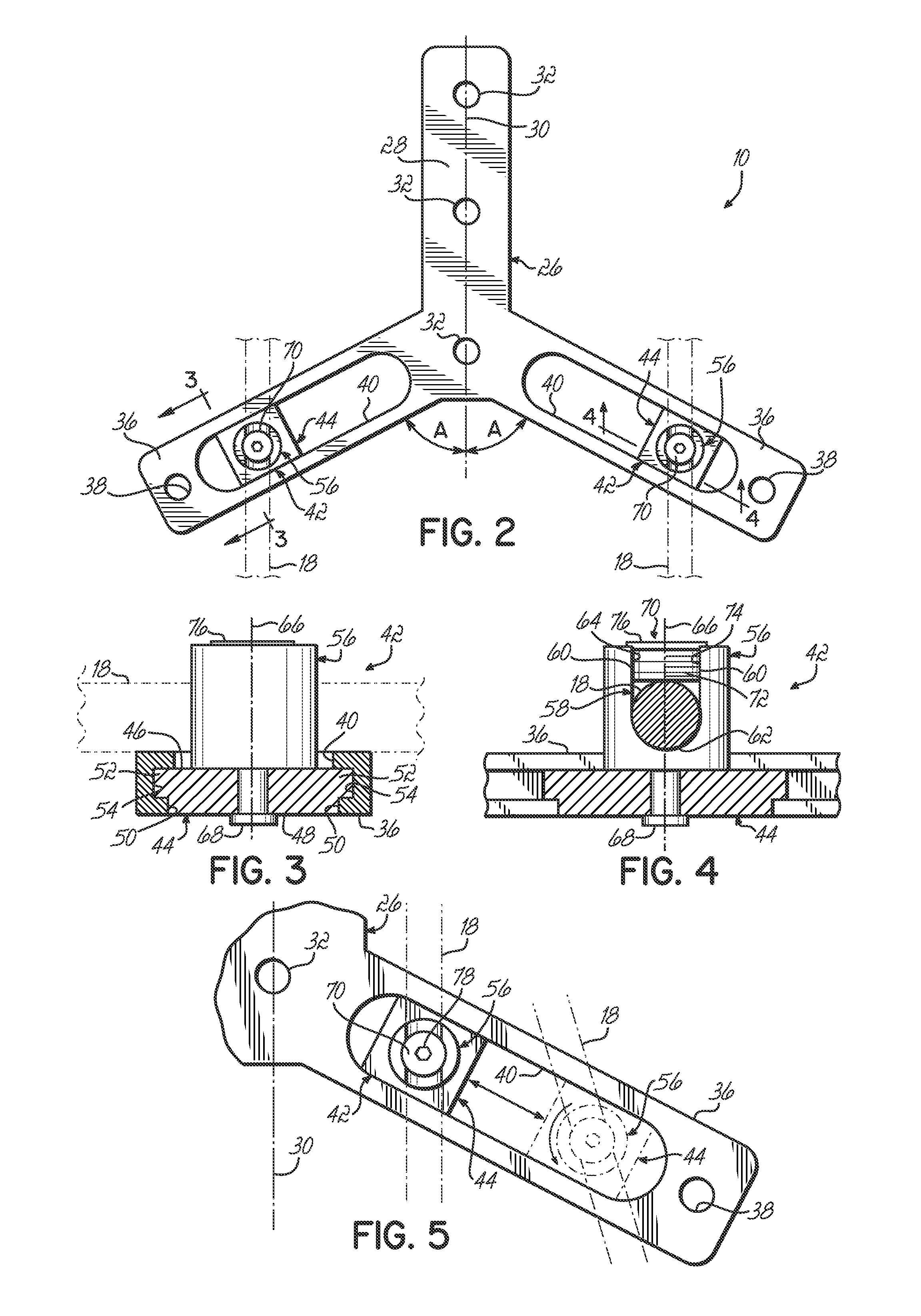
[0005]In one embodiment, the occipital plate includes a base with an elongate central section oriented with a midline of the base. A pair of angled sections extends from the central section on opposite sides of the midline and forms an angle with respect to the midline. The angled sections include attachment assemblies for securing one of the rods to the occipital plate. The attachment assemblies have multi-adjustability features. To this end, at least a portion of the attachment assemblies is rotatable with respect to the base so that the rods may be coupled to the occipital plate at a variety of angles with respect to the midline. In this way, the adjustability of the attachment assemblies may accommodate any misalignments in the rods. Additionally, the position of the attachment assemblies relative to the midline of the occipital plate is adjustable to thereby provide for medial-lateral adjustability when attaching the rods to the occipital plate as part of the OCT construct.
[0007]Therefore, as a result of this invention, a single occipital plate may be utilized for a variety of patient sizes and configurations and provides efficient and secure multi-adjustability, i.e., both angular adjustability and adjustability in a medial-lateral direction, when attaching the rods as part of an OCT construct.

Problems solved by technology

This results in a higher cost of the assembly and a need to maintain separate inventory of the various size and geometry occiput plates.
It also increases the surgical time because the surgeon must search for the device that best fits the patient.
Misalignment of the rods with the plates results in the surgeon making ad hoc adjustments to the device, which further increases the surgical time.

Method used


Image

  • Adjustable occipital plate
  • Adjustable occipital plate
  • Adjustable occipital plate

Examples


Embodiment Construction

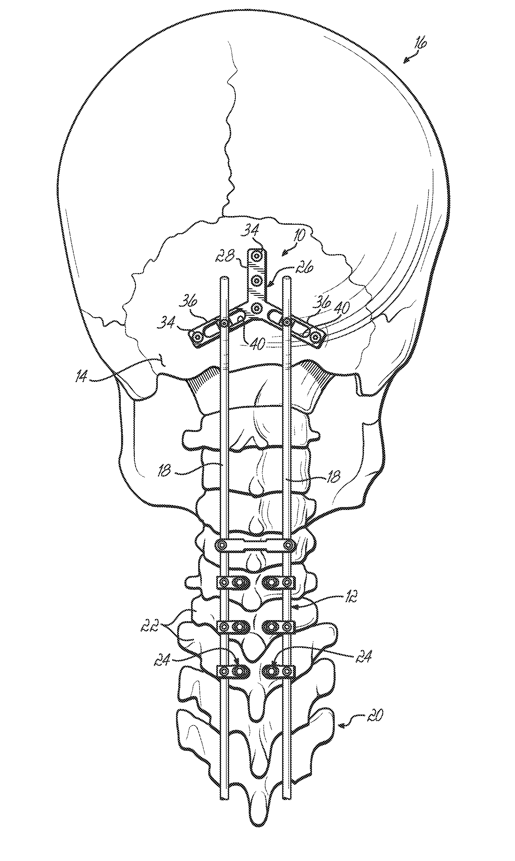
[0023]Referring to FIG. 1, one embodiment of an adjustable occipital plate 10 according to this invention is shown utilized as part of an occipito-cervico-thoracic (OCT) construct 12. The adjustable occipital plate 10 in FIG. 1 is mounted to the occipital bone 14 of a patient 16. One or more rods 18 are attached to the occipital plate 10 and run substantially along the spine 20 of the patient 16 and are attached to various segments of the spine 20 such as selected vertebrae 22 by vertebral mounts 24 according to any one of a know variety of such devices.

[0024]As shown in FIG. 2, the occipital plate 10 according to this embodiment of the invention includes a base plate 26 having an elongate central section 28 with a midline 30, which is generally aligned with the spine 20 when mounted to the occipital bone 14. The central section 28 may include a number of holes or apertures 32, three of which are shown, for bone screws 34 to mount the occipital plate 10 to the occipital bone 14 or a...


PUM


Abstract

An occipital plate for use in an occipito-cervico-thoracic (OCT) construct is mounted to a patient's occipital bone. The occipital plate includes an elongate central section aligned with a midline of the base and a pair of angled sections that project away from the central section and include attachment assemblies for securing a rod to the occipital plate. The attachment assemblies have multi-adjustability features. At least a portion of the attachment assemblies is rotatable with respect to the base so that the rods may be coupled to the occipital plate at a variety of angles with respect to the midline. The angular adjustability may accommodate any misalignments in the rods. Additionally, the position of the attachment assemblies relative to the midline of the occipital plate is adjustable to thereby provide for medial-lateral adjustability when attaching the rods to the occipital plate as part of the OCT construct.

Description

FIELD OF THE INVENTION[0001]This invention relates generally to fixation devices used in orthopedic surgery. The invention relates more particularly to devices used for cervical posterior fixation utilizing a plate attached to a bone in the occipital region and secured to a rod which attaches to a cable, wire, plate, or screw fastened in the spinal region.BACKGROUND OF THE INVENTION[0002]Fixation devices are used in orthopedic surgery to stabilize bones such as those in the spinal column. One type of fixation device includes a plate attachable to a portion of a bone. The plate may be connected to another bone or another portion of the same bone, directly or through other connecting devices. For example, posterior fixation devices can include a plate fastened to the skull, or occiput, one or more rods running longitudinally along the spine and connected to the plate, and vertebral mounts such as plates, cables, wires, hooks, screws, or other connectors attached to a vertebra and conn...

Claims


Application Information

Patent Timeline
Patent Type & Authority Applications(United States)
IPC IPC(8): A61B17/58A61B17/08
CPCA61B17/80A61B17/7055
Inventor HOFFMAN, ZACHARY M.MYERS, MARK A.
Owner ZIMMER BIOMET SPINE INC
Learn More