
Double reflex printing

a printing system and double-reflex technology, applied in the field of double-reflex printing, can solve the problem that the printing technique may still be subject to misregistration errors

Inactive Publication Date: 2008-05-29
XEROX CORP
View PDF7 Cites 73 Cited by
  • Summary
  • Abstract
  • Description
  • Claims
  • Application Information

AI Technical Summary

Problems solved by technology

In situations where the belt or web exhibits any sizeable amount of stretch or deformation, reflex printing techniques may still be subject to misregistration errors.

Method used


Image

  • Double reflex printing
  • Double reflex printing
  • Double reflex printing

Examples


Embodiment Construction

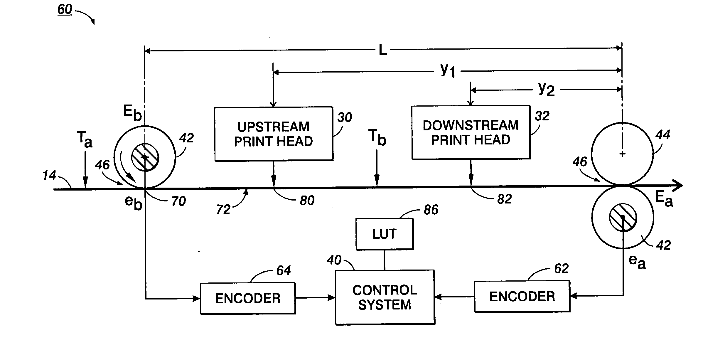
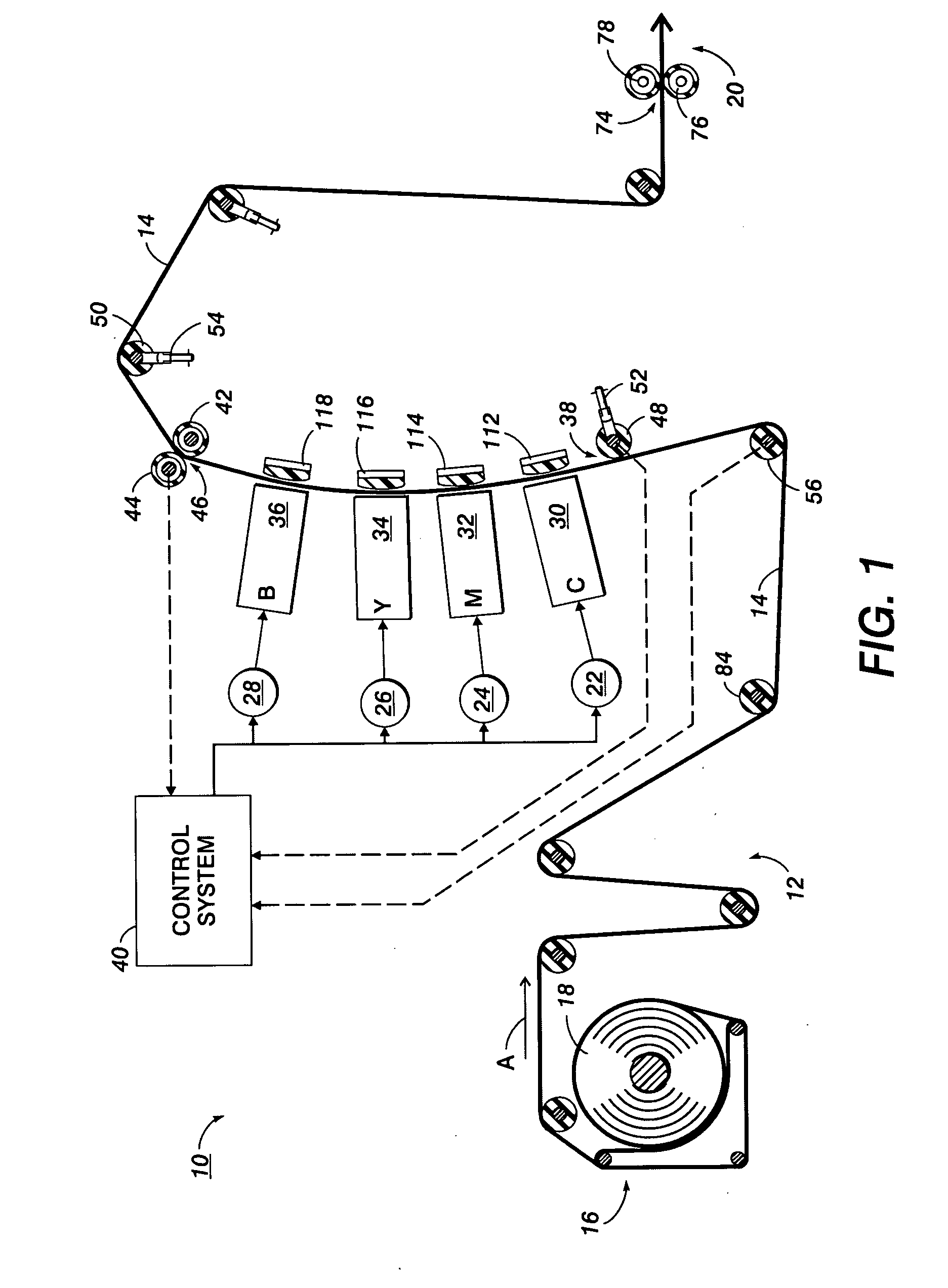
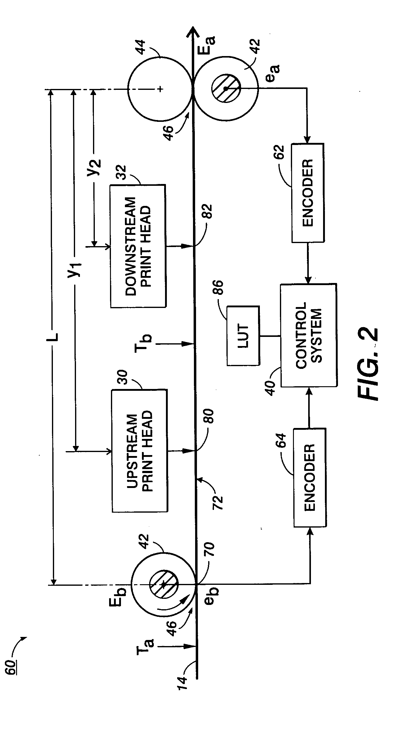
[0018]Aspects of the exemplary embodiment relate to an imaging device and to a registration system for an imaging device. The imaging device includes an extensible image receiving member, such as a web or belt, which defines an image receiving surface that is driven in a process direction between marking stations. The process direction speed of the image receiving surface may vary over its length from a nominal set speed due, for example, to variations in stretch or deformation of the image receiving member and may vary over time due, for example to minor variations in the drive speed. The imaging surface thus has two degrees of freedom, defined by its speed and relative stretch in the receiving member.

[0019]The imaging device can include any device for rendering an image on print media, such as a copier, laser printer, bookmaking machine, facsimile machine, or a multifunction machine, all of which may generally be referred to as printers. The operation of applying images to print m...


PUM


Abstract

A registration system suited to use in an imaging system, such as an inkjet printer, includes a first measuring device, such as an encoder, which provides information for monitoring a speed of a moving image receiving surface of the imaging system, such as a paper web. A second measuring device, such as a second encoder or a tension measuring device, provides information for monitoring a tension in the image receiving surface. A control system determines an actuation time for one of two marking stations, based on the information from the first and second measuring devices. This enables a registration of images applied to the image receiving surface by the two marking stations to take into account both changes in speed of the web and changes in tension in the web.

Description

BACKGROUND[0001]The exemplary embodiment relates to registration of images in printing systems. It finds particular application in connection with a registration system for a multicolor printing system which compensates for fluctuations in the position of an image receiving surface between marking stations.[0002]To provide accurate printing of images, multicolor digital marking systems need to maintain adequate color to color registration. In systems that utilize an elongate image receiving surface, such as a paper web or a belt, the receiving surface reaches a first marking station where a marking material of a first color is applied to the surface, e.g., by firing ink jets, exposing an image on a photoconductive material, or applying toner particles to a selectively imaged photoconductive member. The receiving surface then moves on to a second marking station, where an image or marking material of a second color is applied, and so forth, depending on the number of colors. The timi...

Claims


Application Information

Patent Timeline
Patent Type & Authority Applications(United States)
IPC IPC(8): G03G15/00
CPCG03G15/0152G03G15/0163G03G2215/0158G03G2215/0106
Inventor FOLKINS, JEFFREY J.
Owner XEROX CORP
Learn More