Dual seal for optimized performance

a dual-seal technology, applied in the direction of bearings, shafts and bearings, bearing components, etc., can solve the problems of limited reservoir volume, substantial loss of lubricant from capillary seals,

Active Publication Date: 2008-05-01
EVAULT
View PDF7 Cites 10 Cited by
  • Summary
  • Abstract
  • Description
  • Claims
  • Application Information

AI Technical Summary

Problems solved by technology

However, lower viscosity lubricating fluids typically have higher vapor pressure that results in a substantial amount of lubricant being lost from the capillary seal by evaporation and oil vapor diffusion in the gas phase over the life of the motor.
The available reservoir volume is, however, limited by motor size constraints and requirements for seal splash robustness during shock events.

Method used


Image

  • Dual seal for optimized performance
  • Dual seal for optimized performance
  • Dual seal for optimized performance

Examples


Embodiment Construction

[0016]In the following detailed description, “a” and “an” refer to one or more. The following description is presented to enable a person of ordinary skill in the art to make and use various aspects and embodiments of the invention. Descriptions of specific materials, techniques, and applications are provided only as examples. Various modifications to the examples described herein will be readily apparent to those skilled in the art, and the general principles defined herein may be applied to other examples and applications without departing from the spirit and scope of the invention.

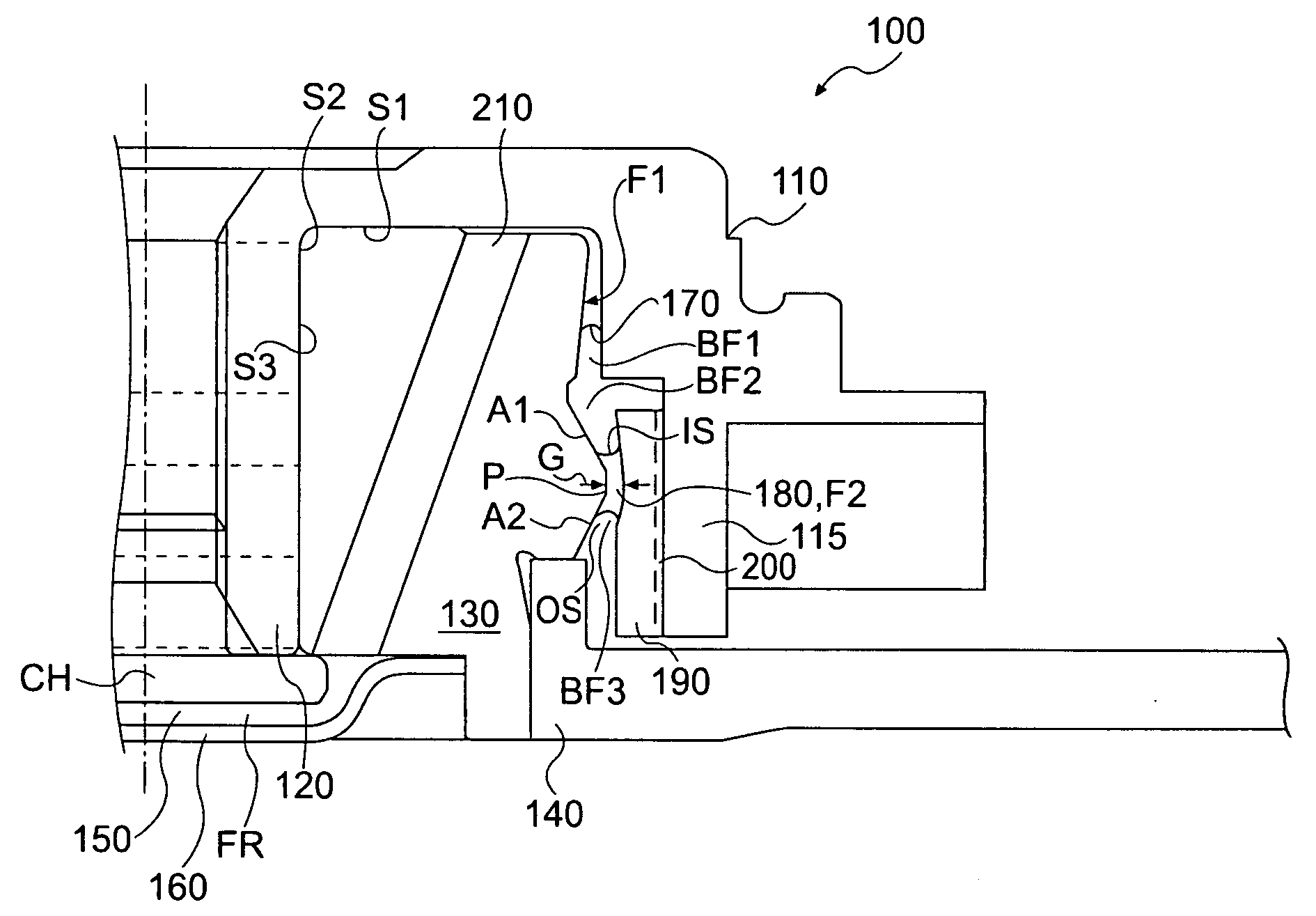
[0017]The present invention contemplates a spindle motor utilizing two capillary seals having different fluids. One of the fluids is optimized for low evaporation rate, while the other is optimized for lubrication and maximizing spindle motor performance. Lubricant loss in capillary-sealed fluid dynamic bearings occurs by evaporation of fluid molecules from the capillary seal and diffusion of those flui...


PUM


Abstract

A fluid dynamic bearing having a hub, a sleeve, and a sealing arrangement comprising a first capillary seal substantially retaining a first fluid and a second capillary seal comprising a second fluid. The second capillary seal is located between the first capillary seal and an opening between the hub and the sleeve.

Description

FIELD OF INVENTION[0001]The present invention relates generally to an improved sealing arrangement for a fluid bearing. This invention relates more specifically to a dual seal arrangement for a fluid dynamic bearing in a disc drive spindle motor.BACKGROUND[0002]Magnetic discs with magnetizable media are used for data storage in most computer systems. Current magnetic hard disc drives operate with the read-write heads only a few nanometers above the disc surface and at rather high speeds, typically a few meters per second.[0003]Generally, the discs are mounted on a spindle that is turned by a spindle motor to pass the surfaces of the discs under the read / write heads. Spindle motors generally include a shaft, a base plate, a sleeve, and a hub. The shaft may be separate from and attached to the hub or incorporated in the hub. The shaft and the rotate relative to each other. Either the shaft rotates and the sleeve remains stationary, or vice versa. Permanent magnets attached to the hub ...

Claims


Application Information

Patent Timeline
Patent Type & Authority Applications(United States)
IPC IPC(8): F16C32/06
CPCF16C33/10F16C41/008F16C2370/12F16C33/74F16C33/745
Inventor PARSONEAULT, NORBERT S.NOTTINGHAM, ROBERT A.PARKHOMOVSKY, ALEXANDERPELSTRING, ROBERT M.LEBLANC, JEFFRY A.HERNDON, TROY M.
Owner EVAULT
Why Eureka
Try Eureka