
Inserter instrument and implant clip

a technology of inserting instruments and implants, applied in the field of inserting instruments and implant clips, can solve the problems of pain, postural problems, injury to the patient, etc., and achieve the effect of reducing the amount of time required

Active Publication Date: 2008-03-20
DEPUY SYNTHES PROD INC +1
View PDF99 Cites 6 Cited by
  • Summary
  • Abstract
  • Description
  • Claims
  • Application Information

AI Technical Summary

Benefits of technology

[0009] Optional elements can include a knob, a drag adjustment screw, at least one protrusion, and a depth control member. The knob can be mechanically coupled to the outer sleeve for causing the outer sleeve and the inner shaft to be rotated about the frame. The drag adjustment screw can provide tension between the trigger mechanism and the inner shaft. The at least one protrusion can be located on the outer sleeve for slidably engaging a distraction instrument. The depth control member can be slidably coupled to the outer sleeve for providing a predetermined insertion depth of the implant.
[0012] There is also provided an implant clip for aligning an implant endplate radially, providing a lordotic angle for implantation, packaging the implant, holding the implant during the implant sterilization process, and protecting the surgeon from being cut by protrusions on a surface of the implant. The implant clip, includes (i) a first member; (ii) a second member pivotally coupled to each other, the coupling causing the implant clip to have a closed position and an open position, (iii) a first implant holder pivotally coupled to the first member, and (iv) a second implant holder, the second implant holder pivotally coupled to the second member, a surface of the first implant holder and a surface of the second implant holder remaining substantially parallel to each other while the first member and the second member pivot between the closed position and the open position. The first member and the second member can be shells. The implant clip can also include a spring for directing the implant clip toward a closed position.
[0013] Each holder can define a depression, where each depression is angled with respect to its holder. Each depression can also be made from a conformable material. The second holder can include a pair of pins that slidably engage a respective pair of cylindrical cavities in the first holder, thereby causing the surface of each holder to remain substantially parallel to each other while the first member and the second member pivot between the closed position and the open position. Alternatively, the first holder and the second holder can include a respective pin and a respective cylindrical cavity that slidably engage each other, thereby causing the surface of each holder to remain substantially parallel to each other while the first member and the second member pivot between the closed position and the open position. Each holder can also include at least one alignment protrusion for aligning of an implantation instrument with the implant clip.
[0019] The invention has many advantages. For example, the invention provides safe one-handed insertion of an implant into a prepared disc space. The invention reduces the amount of time required to complete the surgical procedure. The invention also provides for various manipulations of the implant without physically contacting the implant. For example, the invention can align an endplate of the implant radially and provide a lordotic angle for implantation, the invention can be used for packaging the implant, and the invention can be used to hold the implant during the implant sterilization process.

Problems solved by technology

Spinal surgery involves many challenges as the long-term health and mobility of the patient often depends on the surgeon's technique and precision.
These protrusions are often sharp and can injure the surgeon's hand, if contacted, during implantation.
The insertion of an article, such as the artificial disc or fusion cage, presents the surgeon with several challenges.
However, if the vertebral bodies are separated, or distracted, to beyond a certain degree, further injury to the patient can occur.
Over-insertion posteriorly, or under-insertion anteriorly of the prosthesis can lead to pain, postural problems and / or limited mobility or freedom of movement.
However, use of these tools to distract the vertebral bodies and insert the artificial disc or spinal fusion cage can prove cumbersome.
These devices are both operated with two-hands and do not provide safety features for preventing injury to a surgeon.

Method used


Image

  • Inserter instrument and implant clip
  • Inserter instrument and implant clip
  • Inserter instrument and implant clip

Examples


Embodiment Construction

[0039] The foregoing and other objects, features and advantages of the invention will be apparent from the following more particular description of preferred embodiments of the invention, as illustrated in the accompanying drawings in which like reference characters refer to the same parts throughout the different views. The same number appearing in different drawings represents the same item. The drawings are not necessarily to scale, with emphasis instead being placed upon illustrating the principles of the invention.

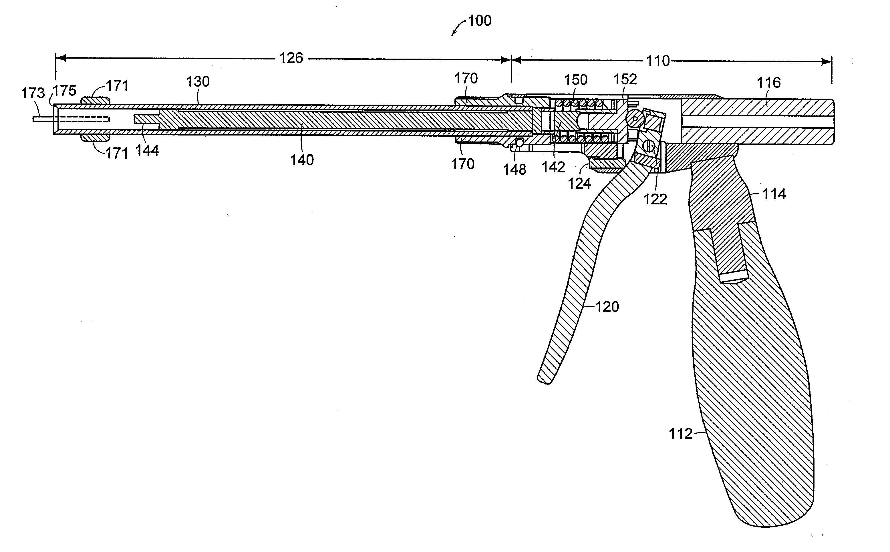
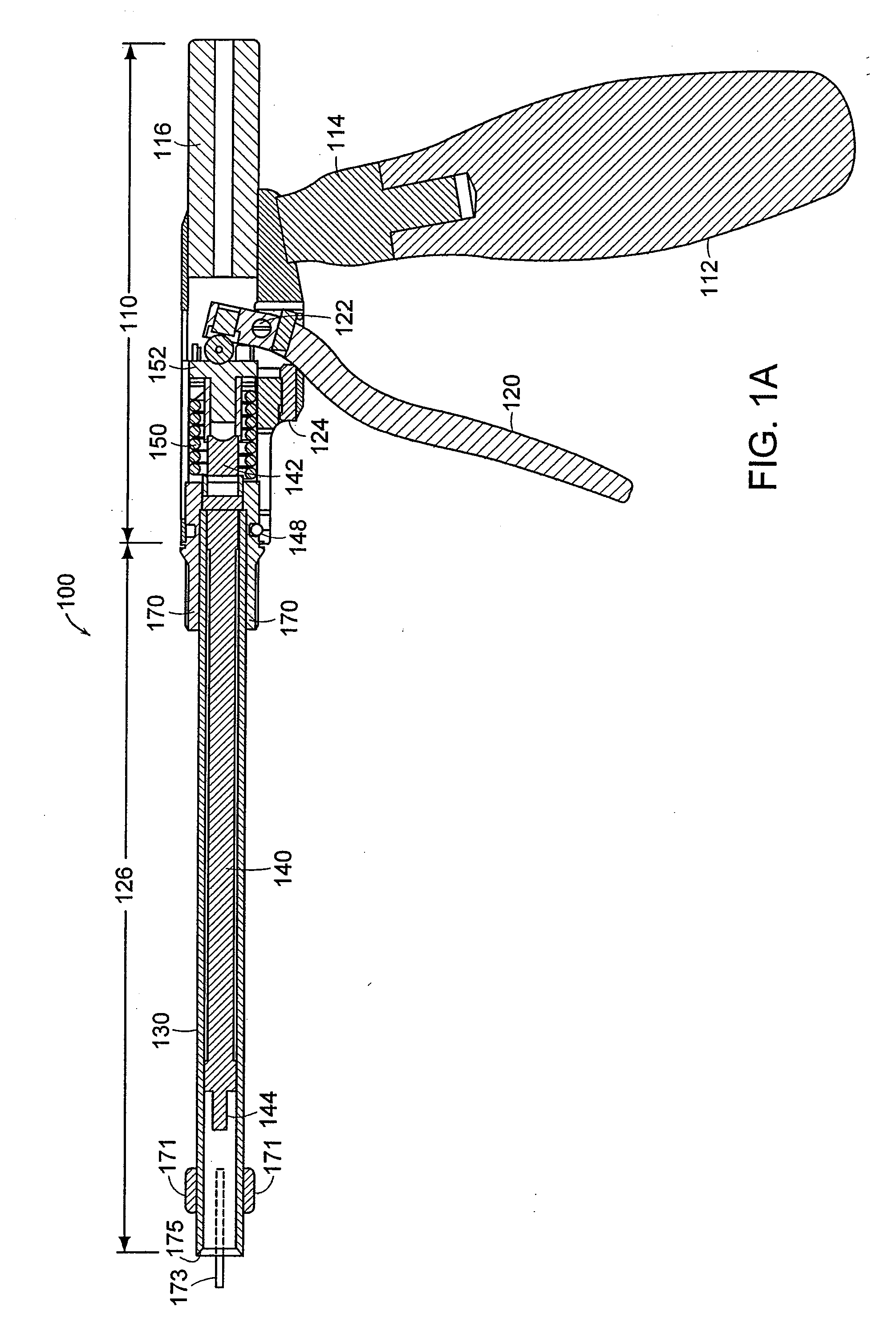
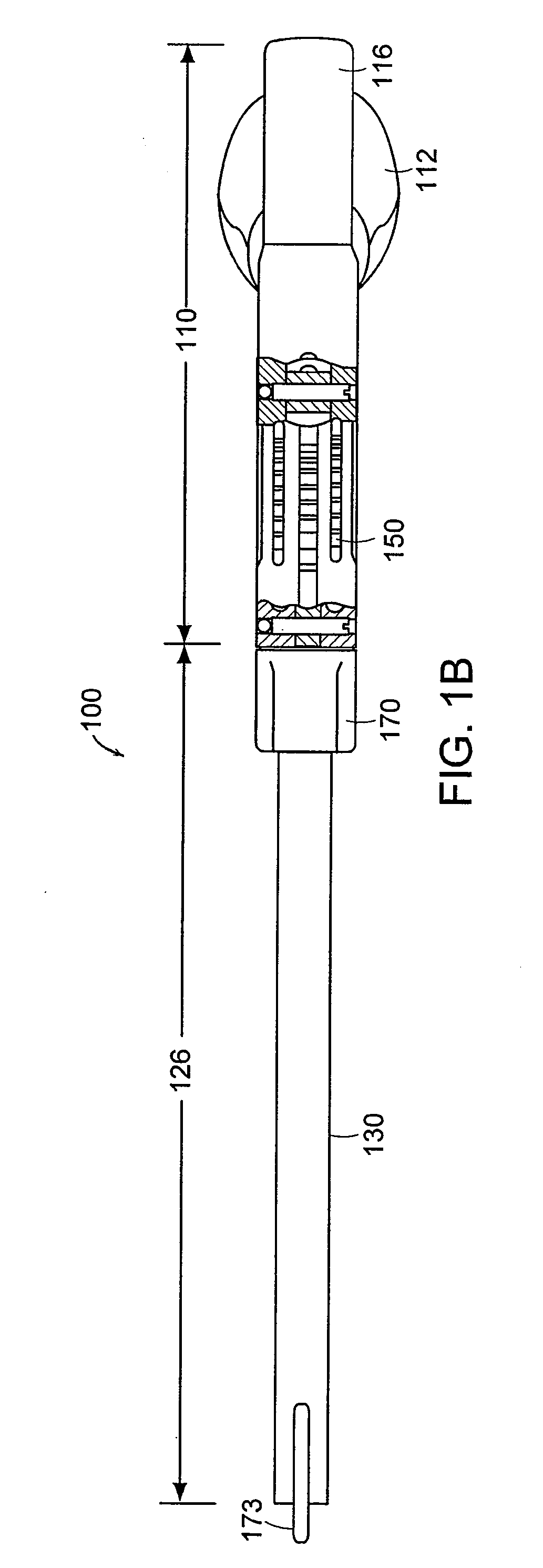
[0040] In general, the present invention is related to apparatus and method for safely inserting an implant into a prepared disc space. The implant can be an artificial disc or spinal fusion cage. Referring to FIGS. 1A and 1B, insertion instrument 100 is shown in a side cross-sectional view and a plan view, respectively. Insertion instrument 100 includes frame or driver body assembly 110, actuator assembly 126 and grabber 160 (FIG. 2A-2C). Insertion instrument 100 is...


PUM


Abstract

A method and apparatus assisting safe one-handed insertion of an implant. An implant implantation device has a frame which includes a trigger mechanism, an outer sleeve mechanically coupled to the frame, an inner shaft having a grabber for mechanically engaging an implant, the inner shaft slidably disposed within the outer sleeve, and a retaining element disposed over the inner shaft for directing the grabber toward a closed position. An implant clip has a first member, a second member pivotally coupled to the first member, a first implant holder pivotally coupled to the first member, the coupling causing the implant clip to have a closed position and an open position, and a second implant holder, the second implant holder pivotally coupled to the second member, a surface of the first implant holder and a surface of the second implant holder remaining substantially parallel to each other while the first member and the second member pivot between the closed position and the open position.

Description

CROSS REFERENCE TO RELATED APPLICATIONS [0001] This application is a divisional of U.S. application Ser. No. 10 / 750,173 filed Dec. 31, 2003, the entire contents of which are hereby incorporated herein by reference.BACKGROUND OF THE INVENTION [0002] Spinal surgery involves many challenges as the long-term health and mobility of the patient often depends on the surgeon's technique and precision. One type of spinal surgery involves the removal of a damaged disc that is located between adjacent vertebral bodies. Procedures are known in which the damaged disc is replaced with an artificial disc or spinal fusion cage. [0003] The artificial disc or spinal fusion cage includes protrusions for engaging the adjacent vertebral bodies to aid in the initial fixation of the artificial disc or spinal fusion cage. These protrusions are often sharp and can injure the surgeon's hand, if contacted, during implantation. [0004] The insertion of an article, such as the artificial disc or fusion cage, pre...

Claims


Application Information

Patent Timeline
Patent Type & Authority Applications(United States)
IPC IPC(8): A61B17/10A61B17/08A61B19/00A61F2/46
CPCA61B2019/303A61B2019/5437A61F2002/4628A61F2002/4627A61F2/4611A61B2090/033A61B2090/3937A61F2/46
Inventor ZALENSKI, EDWARD B.FRANK, DALE W.SORRENTI, MICHAEL D.GRINBERG, ALEXANDER
Owner DEPUY SYNTHES PROD INC
Learn More