Pwm method for cycloconverter
a cycloconverter and cycloconverter technology, applied in the direction of power conversion systems, ac-ac conversion, electrical apparatus, etc., can solve the problems of not being able to reliably detect the direction of current, damage to some circuit components, and less than the desired power transfer
- Summary
- Abstract
- Description
- Claims
- Application Information
AI Technical Summary
Benefits of technology
Problems solved by technology
Method used
Image
Examples
first embodiment
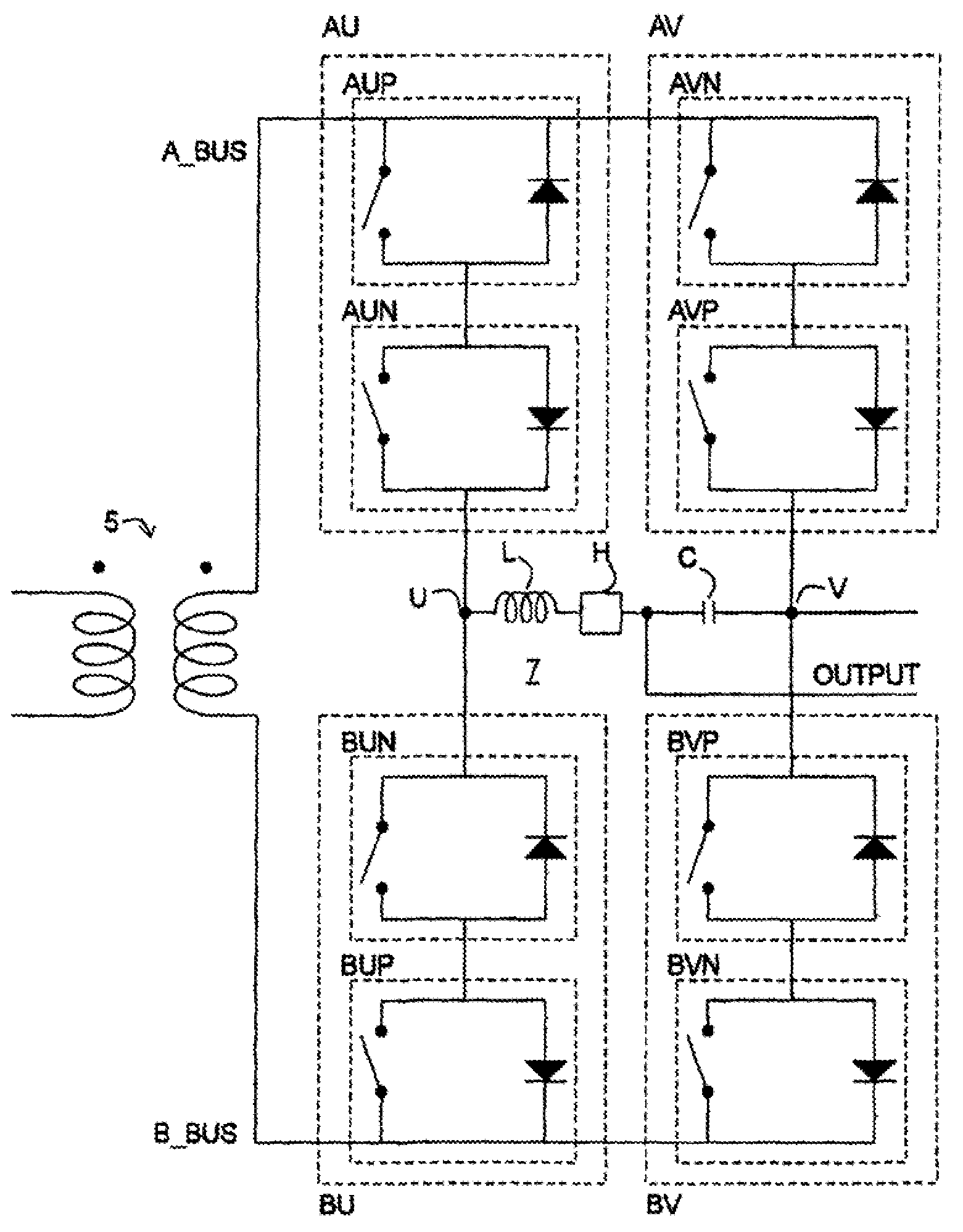
[0079]In a fifth variant of the first embodiment, the method further includes switching a first N topology switch to an on state a second predetermined time after turning the second P topology switch to the off state (S3 of FIG. 11), and switching a second N topology switch to an off state a third predetermined time after turning the first N topology switch to the on state (S4 of FIG. 11). The first, second and third predetermined times need not be equal. However, most commonly, they are equal since they are defined by control signals originating from controller 1.
[0080]In a first example of the fifth variant of the first embodiment, the voltage on the first node A of the first port is positive with respect to the voltage on the second node B of the first port, and the controller is transitioning from a DIRECT state to a ZERO state where nodes U and V are connected to the A_BUS. In this first example of the fifth variant of the first embodiment, the switching of the first P topology...
second embodiment
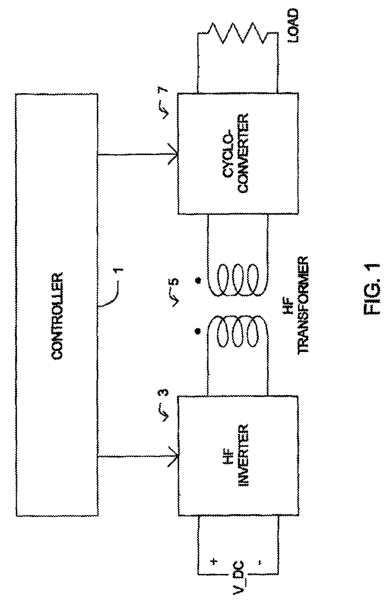
[0090]In a fifth variant of the second embodiment, the method further includes switching a first P topology switch to an on state a second predetermined time after turning the second N topology switch to the off state (S7 of FIG. 12), and switching a second P topology switch to an off state a third predetermined time after turning the first P topology switch to the on state (S8 of FIG. 12). The first, second and third predetermined times need not be equal. However, most commonly, they are equal since they are defined by control signals originating from controller 1.
[0091]In a first example of the fifth variant of the second embodiment, the voltage on the first node A of the first port is positive with respect to the voltage on the second node B of the first port, and the controller is transitioning to a DIRECT state from a ZERO state where nodes U and V are clamped to the A_BUS. In this first example of the fifth variant of the second embodiment, the switching of the first N topolog...
third embodiment
[0101]In a fifth variant of the third embodiment, the method further includes switching a first P topology switch to an on state a second predetermined time after turning the second N topology switch to the off state (S7 of FIG. 12), and switching a second P topology switch to an off state a third predetermined time after turning the first P topology switch to the on state (S8 of FIG. 12). The first, second and third predetermined times need not be equal. However, most commonly, they are equal since they are defined by control signals originating from controller 1.
[0102]In a first example of the fifth variant of the third embodiments the voltage on the first node A of the first port is positive with respect to the voltage on the second node B of the first port, and the controller is transitioning from an inverted state to a ZERO state where nodes U and V are clamped to the A_BUS. In this first example of the fifth variant of the third embodiment, the switching of the first N topolog...
PUM
 Abstract
Description
Claims
Application Information
 - R&D
- Intellectual Property
- Life Sciences
- Materials
- Tech Scout
- Unparalleled Data Quality
- Higher Quality Content
- 60% Fewer Hallucinations
Browse by: Latest US Patents, China's latest patents, Technical Efficacy Thesaurus, Application Domain, Technology Topic, Popular Technical Reports.
© 2025 PatSnap. All rights reserved.Legal|Privacy policy|Modern Slavery Act Transparency Statement|Sitemap|About US| Contact US: help@patsnap.com


