Eureka AIR delivers breakthrough ideas for toughest innovation challenges, trusted by R&D personnel around the world.

Improved ethernet connector

Inactive Publication Date: 2007-12-27
JOHN MEZZALINGUA ASSOC INC
View PDF10 Cites 2 Cited by
  • Summary
  • Abstract
  • Description
  • Claims
  • Application Information

AI Technical Summary

Benefits of technology

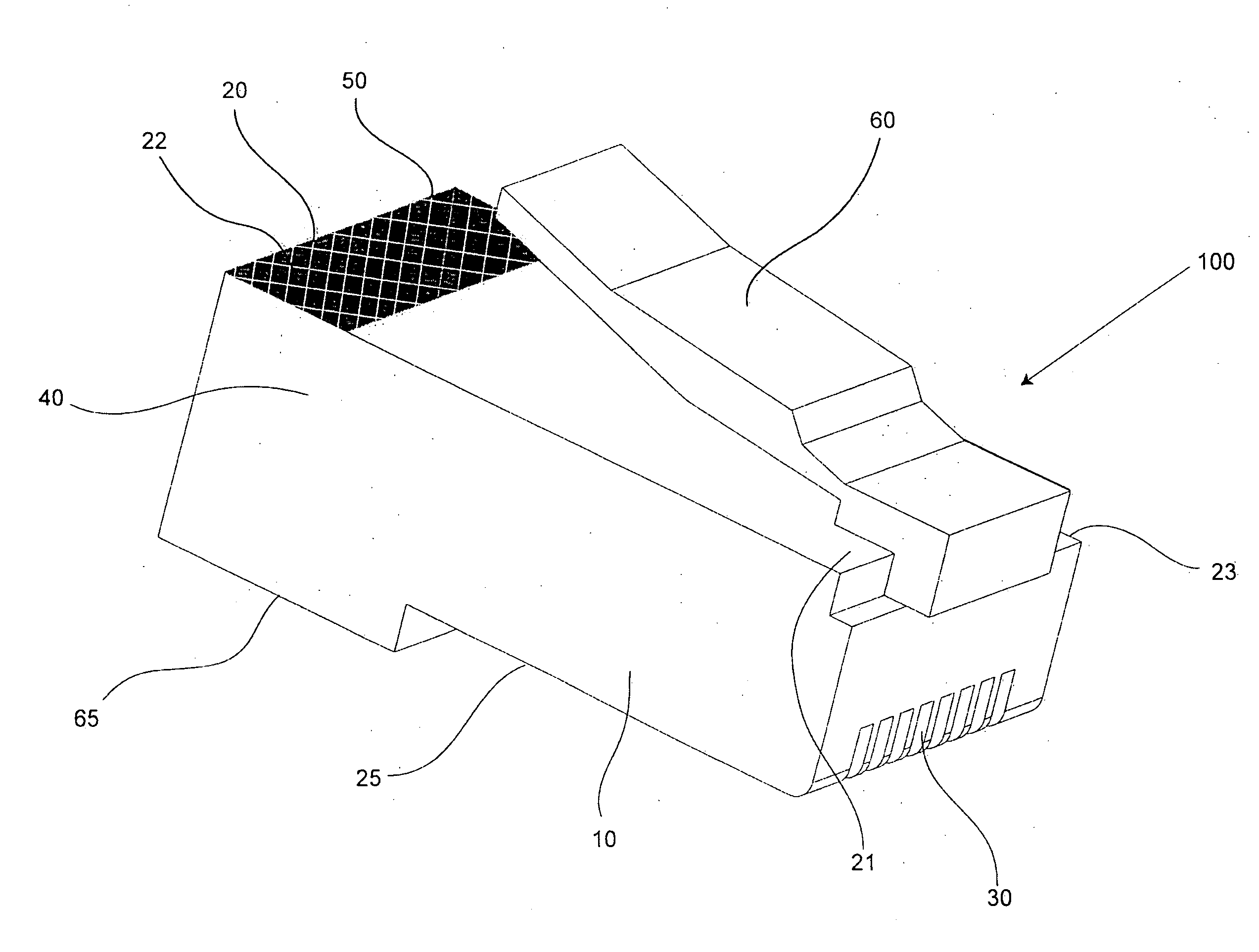
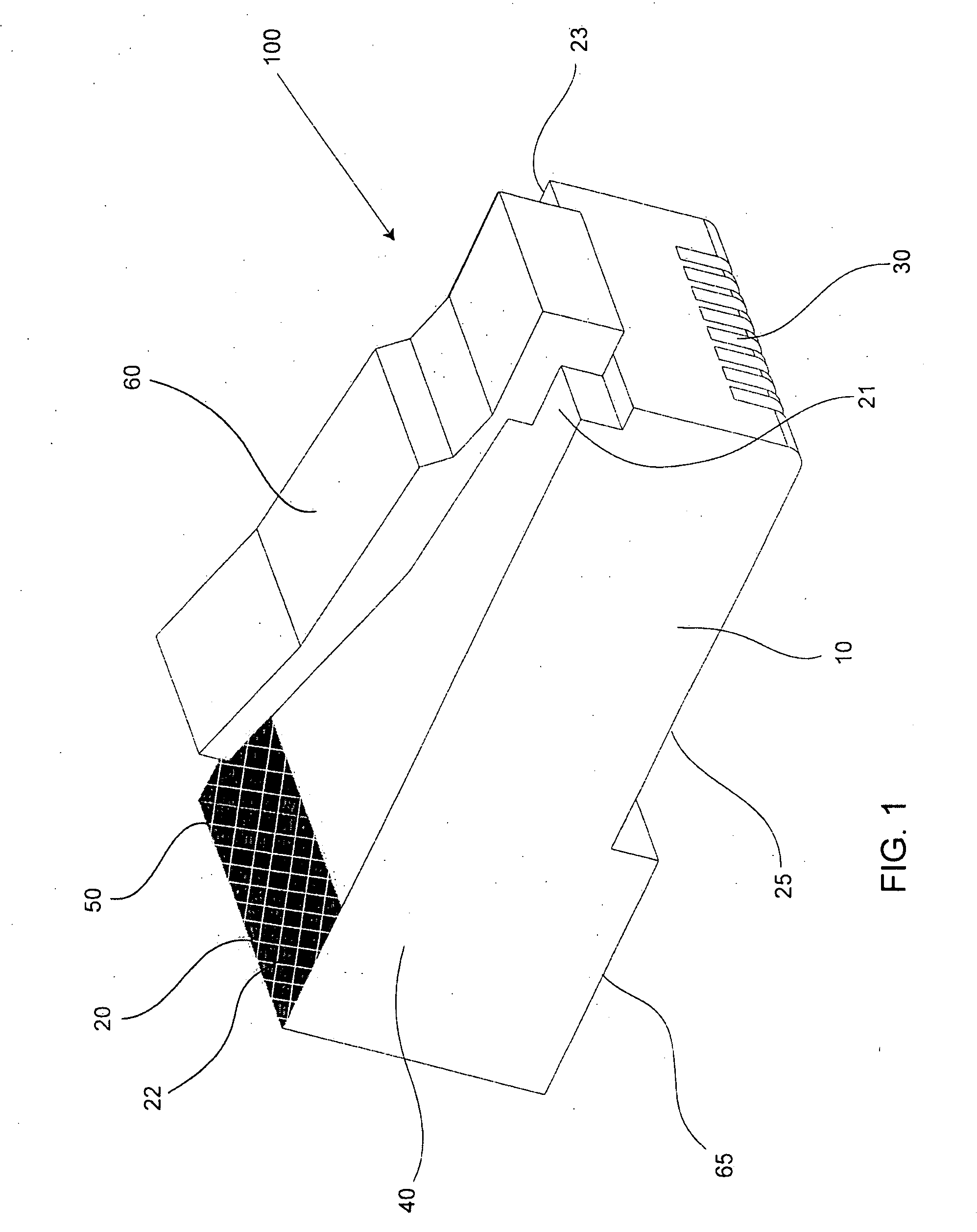
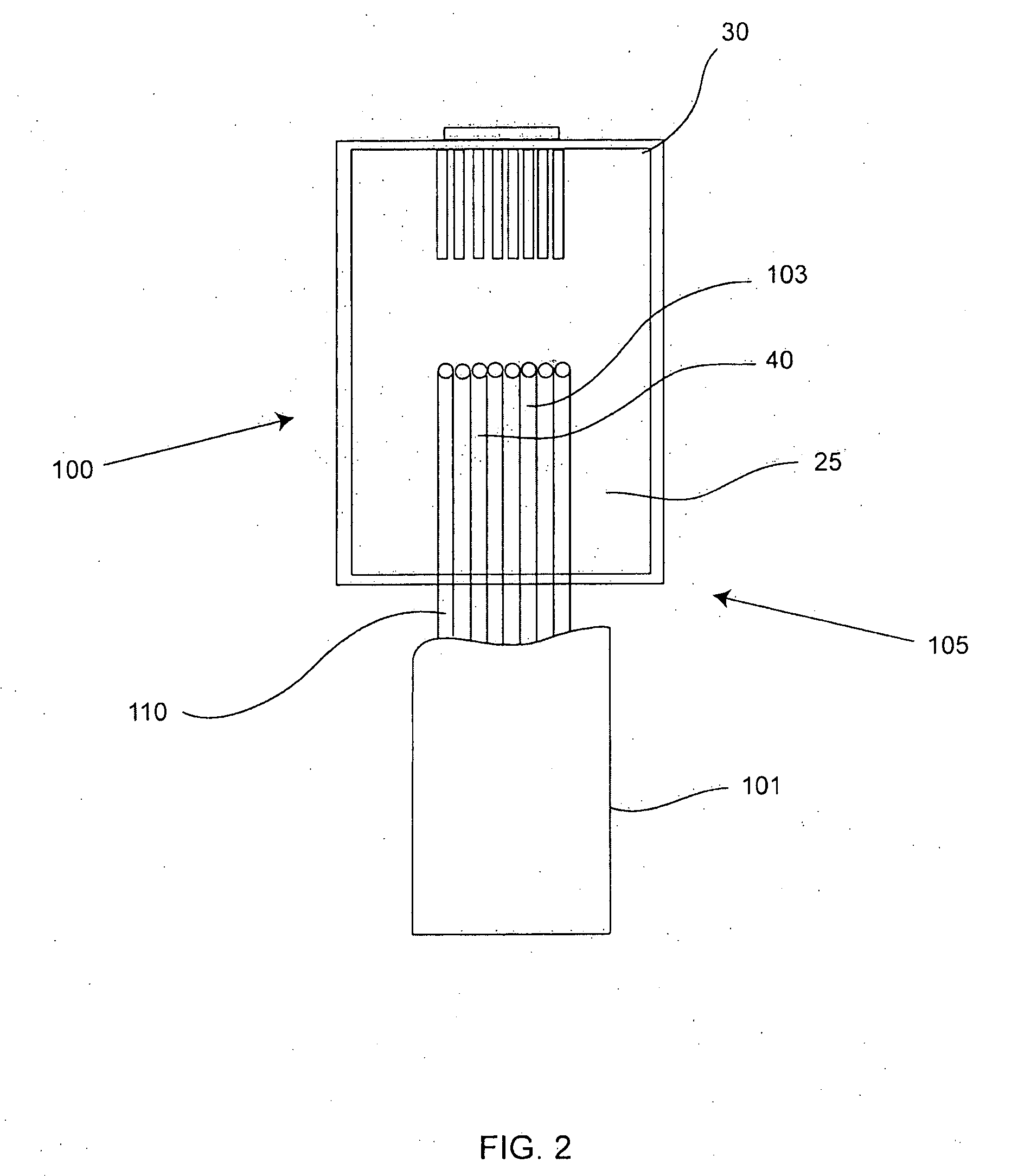
[0006]A third aspect of the present invention provides a method of preventing wire ordering errors in a connector comprising: providing a connector having a body with a transparent side and a non-transparent side and at least two wire receiving chambers having an insulation displacement contact therein; providing a cable with a plurality of different colored wires; providing a wiring order that corresponds to an orientation of the plurality of different colored wires viewed though the transparent side of said connector; inserting the wires into said at least two wire receiving chambers creating an actual wire ordering; and comparing said actual wire ordering with said wire ordering, said comparison including viewing said inserted wires through said transparent side.
[0007]A fourth aspect of the present invention provides a visual check ethernet connector comprising: a transparent body having a top surface, and a bottom surface; at least eight terminals disposed within said transparent body; at least eight chambers configured to accept a wire adjacent said at least one terminal, wherein said at least one chamber can be viewed through said bottom surface of the connector; a means of preventing viewing of said chambers through said top surface.

Problems solved by technology

Furthermore, the very short wire segments often made the risk high of switching the wire order unintentionally, thus leading to the creation of defective connectors.
Additionally, the short wire segments and the typical style IDC made the chance of bad connections a common problem.

Method used


Image

  • Improved ethernet connector
  • Improved ethernet connector
  • Improved ethernet connector

Examples


Embodiment Construction

[0016]Although certain embodiments of the present invention will be shown and described in detail, it should be understood that various changes and modifications may be made without departing from the scope of the appended claims. The scope of the present invention will in no way be limited to the number of constituting components, the materials thereof, the shapes thereof, the relative arrangement thereof, etc., and are disclosed simply as an example of an embodiment. The features and advantages of the present invention are illustrated in detail in the accompanying drawings, wherein like reference numerals refer to like elements throughout the drawings.

[0017]As a preface to the detailed description, it should be noted that, as used in this specification and the appended claims, the singular forms “a”, “an” and “the” include plural referents, unless the context clearly dictates otherwise.

[0018]A first aspect of the present invention provides a visual check connector 100 to address t...


PUM


Abstract

A visual check connector comprising a body having a top surface, and a bottom surface and at least one terminal disposed within the body. The connector has at least one chamber configured to accept a wire adjacent at least one terminal, wherein the chamber can be viewed through the bottom surface of the connector that is transparent and a non-transparent feature positioned proximate the top surface, wherein the feature prevents viewing of the chamber.

Description

FIELD OF THE INVENTION[0001]Ethernet connectors for data cable terminations and connections.BACKGROUND[0002]Communication cables and in particular data cables used for the transmission of information according to the Ethernet standard are commonplace and used in a multitude of environments including commercial offices and buildings, industrial environments, and with increasing frequency, residences. The data cables most commonly used are generally referred to as twisted wire pairs. A typical data cable contains two connectors on both ends to connect a computer to another computer or network device.[0003]The typical connector may be for applications such as ethernet, which uses data cables having twisted pairs of wires within to minimize interference or cross-talk between the individual wires in the cable, which may be required to travel relatively long distances. To prevent unwanted interference in the wires, the length of untwisted wires before entering the connector were kept to a...

Claims


Application Information

Patent Timeline
IPC IPC(8): H01R3/00
CPCH01R4/2404H01R2201/04H01R24/64H01R12/714H01R12/52
Inventor AMIDON, JEREMY
Owner JOHN MEZZALINGUA ASSOC INC
Why Eureka
Eureka Blog
Learn More