
Release mechanisms for a clip device

a release mechanism and clip technology, applied in the field of clips, can solve the problems of gastrointestinal bleeding, a serious condition that is often fatal, and is delivered using rigid shafted instruments via incisions,

Inactive Publication Date: 2007-12-06
COOK MEDICAL TECH LLC
View PDF103 Cites 240 Cited by
  • Summary
  • Abstract
  • Description
  • Claims
  • Application Information

AI Technical Summary

Benefits of technology

[0012] Optionally, stop elements, such as beads, may be disposed on the clip to ensure that the sliding ring is not advanced distally beyond the end of the clip. Further, the stop elements may lockingly engage with the sliding ring to ensure that the sliding ring does not disengage from the clip.
[0013] In alternative embodi

Problems solved by technology

Gastrointestinal bleeding is a somewhat common and serious condition that is often fatal if left untreated.
Although such approaches are often effective, bleeding continues for many patients and corrective surgery therefore becomes necessary.
One of the problems associated with conventional hemostatic devices, however, is that they can only be delivered using rigid shafted instruments via incision or trocar cannula.
Moreover, many of the conventional hemostatic devices are not strong enough to cause permanent hemostasis.
One problem with this clip and other similar types of clips having a pair of arms is that it may often be necessary to rotate the clip to properly grasp the area to be clipped.
Rotation of the clip is often hindered or complicated by the travel of the operating wire through the bends of the tube(s) used to deliver the clip.
Another problem often encountered with conventional hemostatic devices is the difficulty in securing the clip device to the delivery apparatus prior to reaching the target area within the patient, and then quickly and easily releasing the clip device from the delivery apparatus once the clip has been attached to the target site.

Method used


Image

  • Release mechanisms for a clip device
  • Release mechanisms for a clip device
  • Release mechanisms for a clip device

Examples


Embodiment Construction

[0038] In the present application, the term “proximal” refers to a direction that is generally towards a physician during a medical procedure, while the term “distal” refers to a direction that is generally towards a target site within a patent's anatomy during a medical procedure.

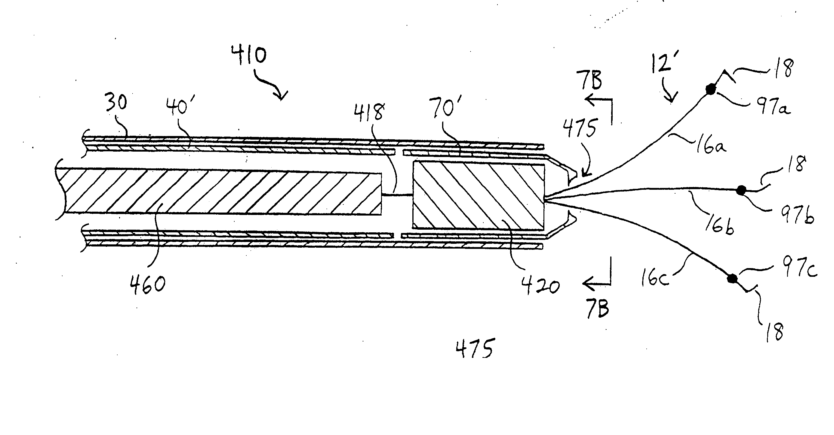
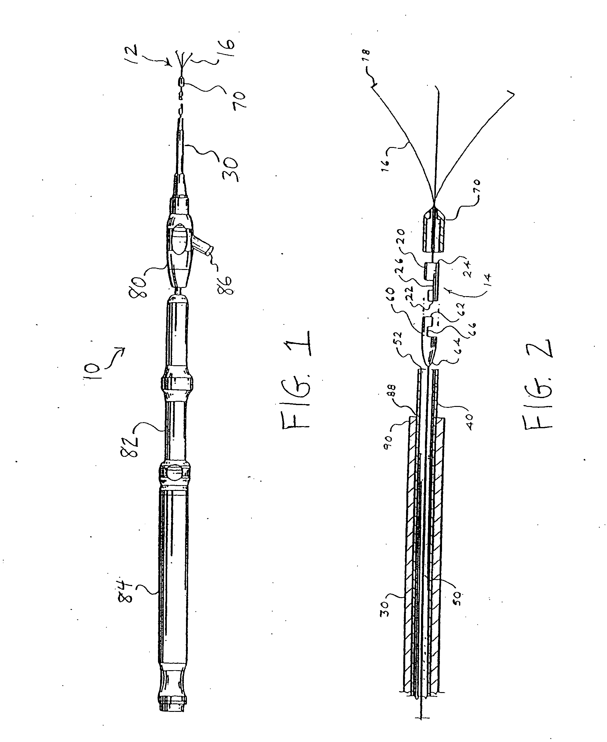
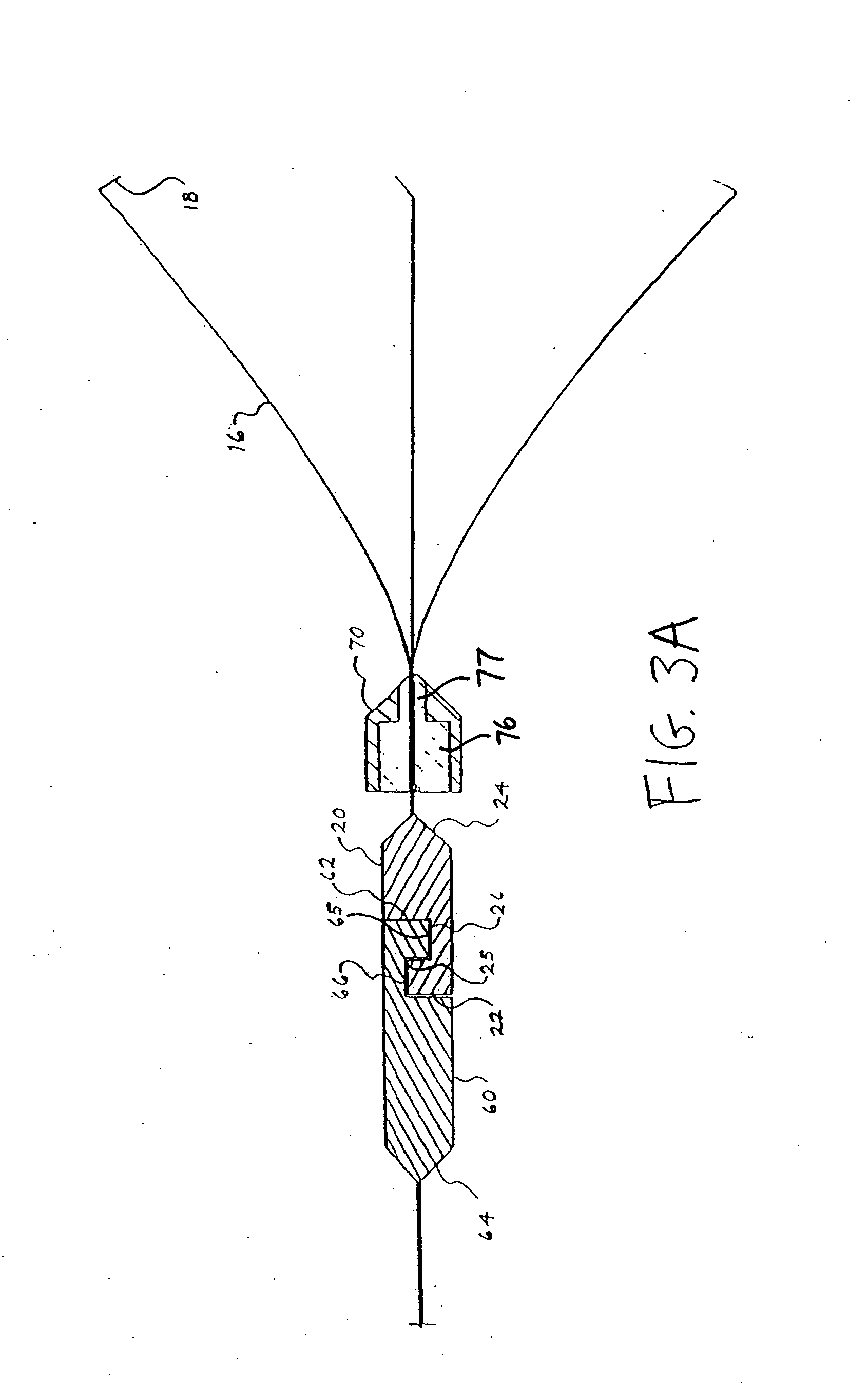
[0039] The present invention provides a clip device for tissue or the like. Referring to FIGS. 1-3A, a first embodiment of a clip device according to the present invention is shown. Clip device 10 includes clip 12 with proximal end 14 having three arms 16 extending from the proximal end. Each arm is preferably inwardly bent at its end 18 to better grasp the tissue. While three arms are preferred, it is contemplated that fewer than or more than three arms may be used. For example, clip 12 may have two or four arms.

[0040] The clip may be made from any suitable resilient material such as stainless steel, nitinol, plastic, and the like. In addition, the arms may have a cross-sectional shape that is round, sq...


PUM


Abstract

A clip device for hemostasis includes a clip having a proximal end portion and at least two arm portions extending from the proximal end portion and provided with a tendency to open. A sliding ring is provided for closing the arm portions of the clip. A first retainer is attached to the clip, and the first retainer is configured to be releasably secured to a second retainer that may be attached to an operating wire or a torque cable. In operation, the clip device is advanced to a target site in a body cavity. An outer sheath is retracted to expose the clip, causing the arms to open. An inner sheath is advanced distally, causing the sliding ring to advance distally to close the arms of the clip. Stop elements may be disposed on the clip to ensure that he sliding ring is not advanced distally over the clip. Then, the first retainer is disengaged from the second retainer. Various mechanisms are disclosed to permit the first and second retainers to disengage from one another. The first retainer, attached to the clip, is left inside the patient's body cavity, while the second retainer is removed from the patient.

Description

PRIORITY CLAIM [0001] This invention claims the benefit of priority of U.S. Provisional Application Ser. No. 60 / 809,912, entitled “Release Mechanisms for a Clip Device,” filed Jun. 1, 2006, the disclosure of which is hereby incorporated by reference in its entirety.TECHNICAL FIELD [0002] The present invention relates to a clip, and more specifically, to a clip that can be used to cause hemostasis of blood vessels along the gastrointestinal tract, or that can be used as an endoscopic tool for holding tissue or the like. BACKGROUND INFORMATION [0003] Conventionally, a clip may be introduced into a body cavity through an endoscope to grasp living tissue of a body cavity for hemostasis, marking, and / or ligating. In addition, clips are now being used in a number of applications related to gastrointestinal bleeding such as peptic ulcers, Mallory-Weiss tears, Dieulafoy's lesions, angiomas, post-papillotomy bleeding, and small varices with active bleeding. [0004] Gastrointestinal bleeding i...

Claims


Application Information

Patent Timeline
IPC IPC(8): A61B17/08
CPCA61B17/0643A61B17/122A61B2019/303A61B2017/0053A61B2017/0641A61B17/1285A61B2090/033
Inventor BROWN, HILBERT D.CHEN, STEVE K.GAYZIK, CAROLINE C.DUCHARME, RICHARD W.KARPIEL, JOHN A.KORNRUMPF, KATHRYN M.SURTI, VIHAR C.
Owner COOK MEDICAL TECH LLC
Learn More