Eureka AIR delivers breakthrough ideas for toughest innovation challenges, trusted by R&D personnel around the world.

Wireless Utility Monitoring And Control Mesh Network

Inactive Publication Date: 2007-09-06
OSAJE EMEKE EMMANUEL
View PDF12 Cites 95 Cited by
  • Summary
  • Abstract
  • Description
  • Claims
  • Application Information

AI Technical Summary

Benefits of technology

[0020] In accordance with some embodiment of the present invention, distributed wireless utility management network, wherein control and access method using code, time, direction and frequency diversity/variations are provided. Wireless utility management is provided to a plurality of location and wireless data access if achieved to and from a plur

Problems solved by technology

In third world countries were a large majority of the population are not literate, it is practically impossible for the utility provider to ask the consumers to provide the meter reading.
In the instance where the employees of the Energy or Utility provider go round the customers premises to capture the meter reading is plagued by diverse factors.
The drawback includes: it might not always be possible for the employee to gain access to the customer meter at the time of visit.
This method also leaves the utility provider lagging the billing cycle.
This will become a recurring expenditure to the provider.
This investment will be worth the initial installation cost if it was deployed in highly populated urban settlements.
For cases where the customers are dispersed over large geographical region, then the investment becomes too expensive to justify the cost.
The limitations suffered by these technologies include: the limit of the range of the radio t

Method used


Image

  • Wireless Utility Monitoring And Control Mesh Network
  • Wireless Utility Monitoring And Control Mesh Network
  • Wireless Utility Monitoring And Control Mesh Network

Examples


Embodiment Construction

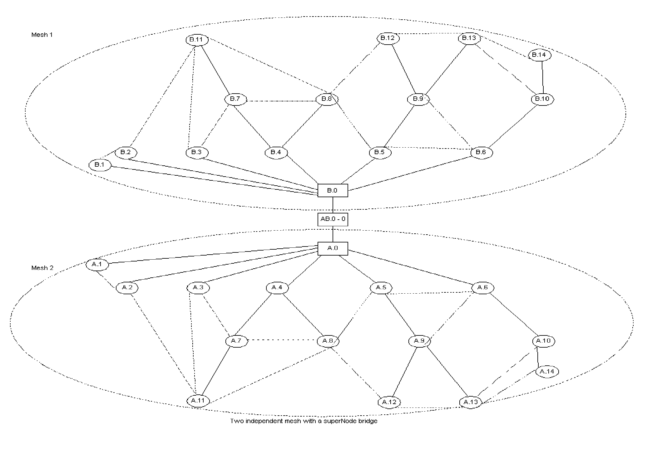
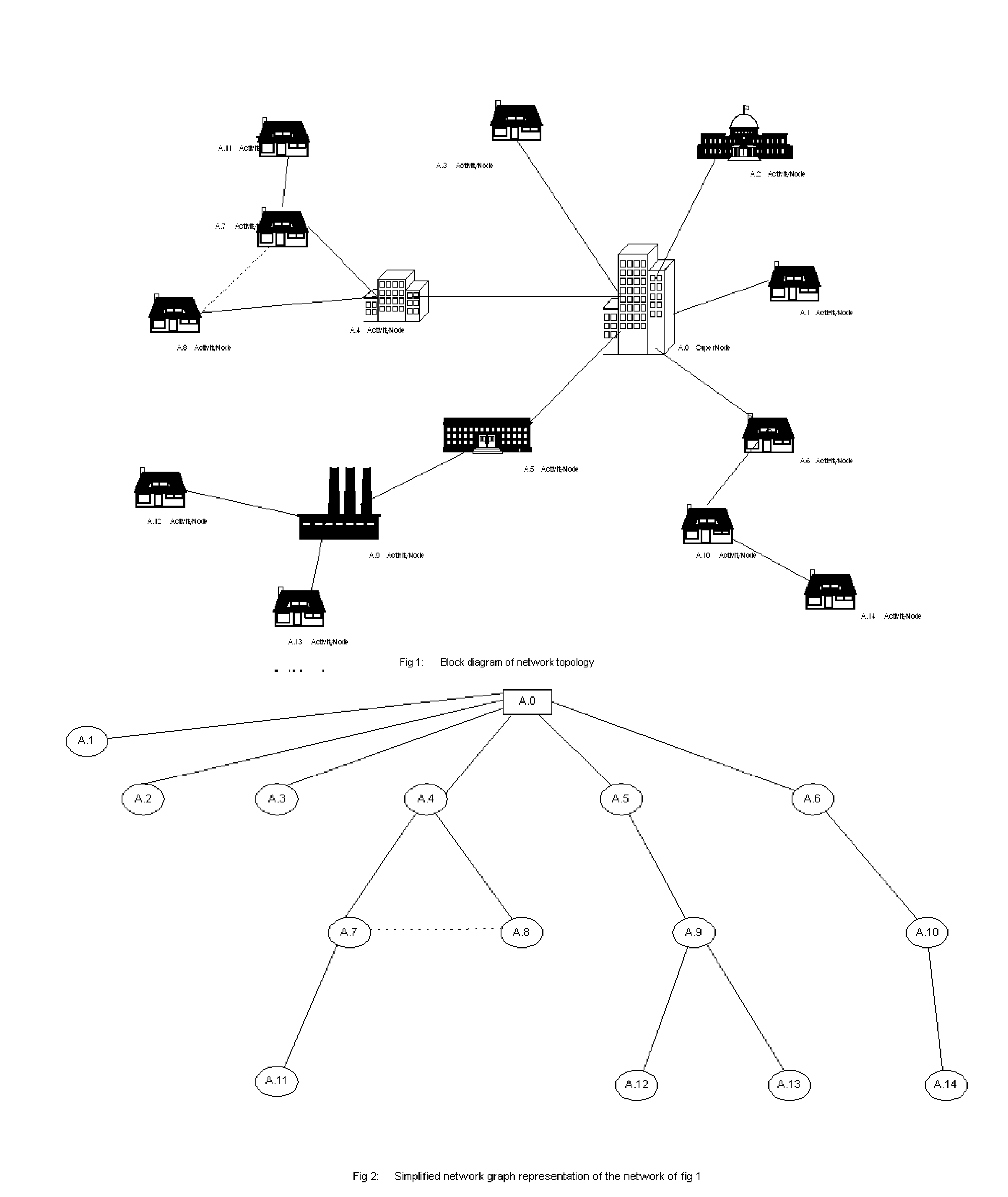
[0038]FIG. 1 is the representation for the network topology in line with an instance of the present invention. For simplicity a block diagram representation is used here and most of the details were not highlighted here; but subsequent diagram will reveal more of the network component details. The network topology include wireless utility management network with plurality of locations. The locations are labeled A.0 to A.16 [These locations will be interchangeably referred to as points, nodes, subscriber, customer in this document]. Although in this drawing the wireless nodes are shown as fixed within the network, but in practical application, due to flexibility of this mesh network, such locations can be mobile (i.e. moved from one part of the network to another or moved across networks).

[0039] The nodes in FIG. 1 are made up of two independent module integrated into one package. The modules are: the intelligent and repeater modules. The modules perform different functions and each...


PUM


Abstract

A scalable distributed wireless control and monitoring system for managing utility supply over a wide geographical area. Such distributed networks can manage/control electricity, gas, water and other petroleum product supply to a large geographical area. The network consist of plurality of nodes that control and monitor utility usage at subscriber point; these nodes are called activityNode. The ActivityNodes can communicate with one or plurality of superNodes. The superNodes act as center for control and management for the activityNodes. The superNode can send “instruction to disconnect” a subscriber to an ActivityNode. A superNode can exchange data with one or plurality of neighboring superNodes. An aggregate of superNodes can poll data from plurality of activityNodes on the network, this information can be analyzed to determine the network performance and can also be use to preempt fault on any part of the network.

Description

BACKGROUND OF THE INVENTION [0001] 1. Field of the Invention [0002] This invention relates to wireless meter monitoring and control for utility supply to subscribers in a wide geographical area, and particular emphasis to monitoring for leaks and failure on petroleum pipeline. [0003] 2. Related Art [0004] Remote telemeter and control for utility supply to urban and rural communities is on the increase. In many cases, Energy and utility supplier rely on the customers to provide the meter reading. In societies where communication infrastructures are well developed, the customer send the meter reading to the utility provider through any of the available communication media. [0005] In third world countries were a large majority of the population are not literate, it is practically impossible for the utility provider to ask the consumers to provide the meter reading. When the Energy or the utility provider realize that they cannot get most the utility meter reading through the customers,...

Claims


Application Information

Patent Timeline
IPC IPC(8): H04B7/14H04J3/08H04J1/10
CPCG01D4/004H04B7/155H04W28/04H04W74/06H04W84/18Y04S20/42Y04S20/322Y02B90/245Y02B90/246Y04S20/40Y02B90/242H04Q2209/40Y02B90/20Y04S20/30
Inventor OSAJE, EMEKE EMMANUEL
Owner OSAJE EMEKE EMMANUEL
Why Eureka
Eureka Blog
Learn More