
Medical Imaging Systems

a medical imaging and system technology, applied in the field of absorption and fluorescent dyes, can solve the problem of not teaching how the system might be adapted

Active Publication Date: 2007-08-30
BETH ISRAEL DEACONESS MEDICAL CENT INC
View PDF32 Cites 156 Cited by
  • Summary
  • Abstract
  • Description
  • Claims
  • Application Information

AI Technical Summary

Benefits of technology

[0005] A medical imaging system provides simultaneous rendering of visible light and diagnostic, or functional, images. The system may be portable, and may include adapters for connecting various light sources and cameras in ope

Problems solved by technology

As a disadvantage, the Imaizumi patent discloses a system with complex optics and hardware, and does not teach how the system might be adapted for use in open surgical applications such as surgical pathology.

Method used


Image

  • Medical Imaging Systems
  • Medical Imaging Systems
  • Medical Imaging Systems

Examples


Embodiment Construction

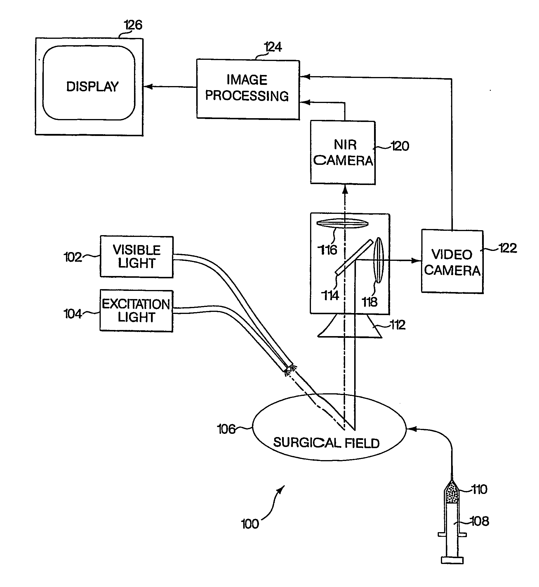
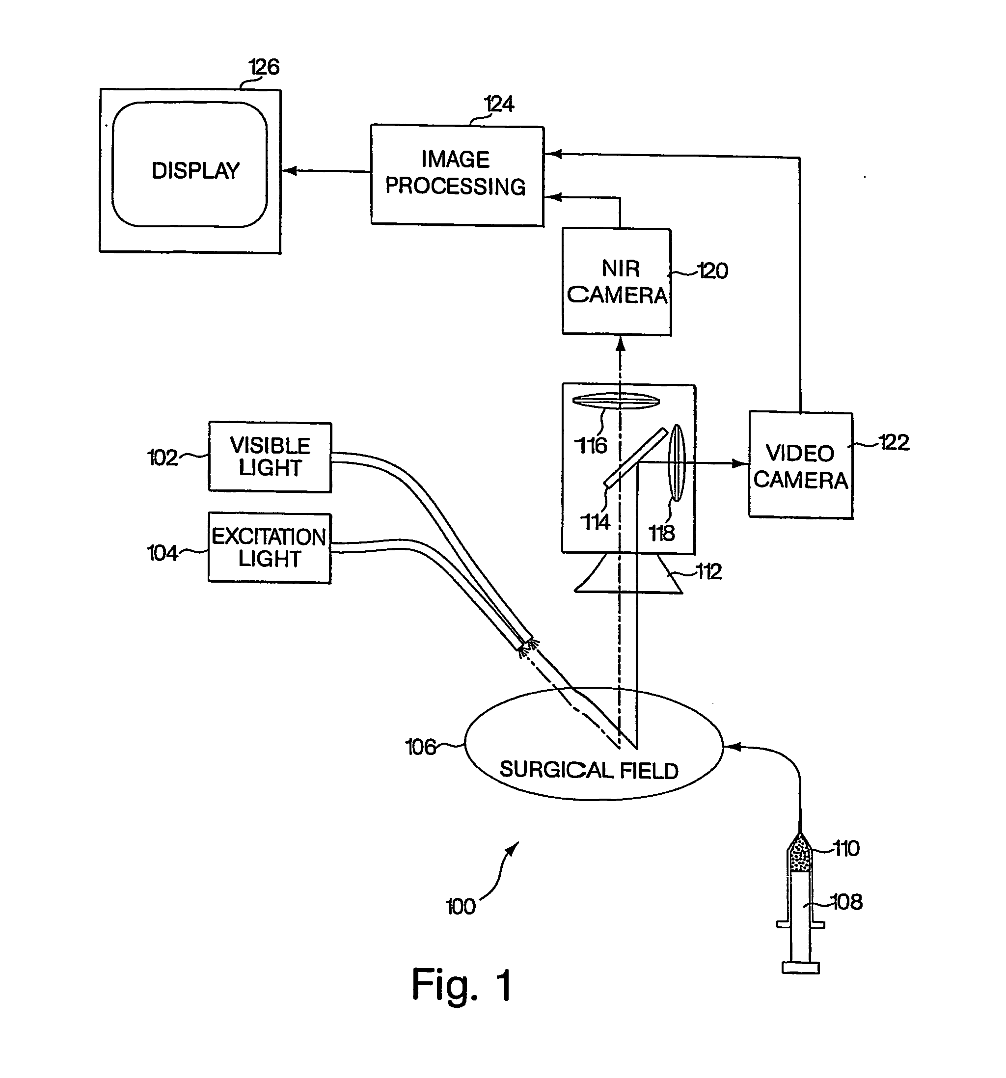
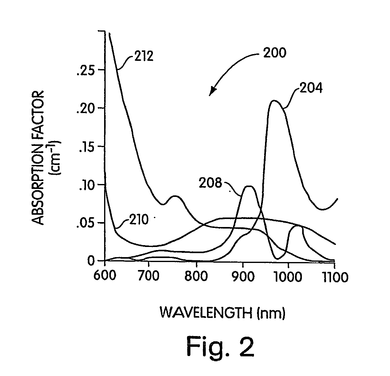
[0015] To provide an overall understanding of the invention, certain illustrative embodiments will now be described, including a system for generating superimposed circulatory and tissue images in video format. However, it will be understood that the methods and systems described herein can be suitably adapted to other medical imaging applications where visible light tissue images may be usefully displayed with diagnostic image information obtained from outside the visible light range and superimposed onto the visible light image. More generally, the methods and systems described herein may be adapted to any imaging application where a visible light image may be usefully displayed with a superimposed image captured from areas within the visible light image that are functionally marked to emit photons outside the visible light range (or in certain circumstances, within a specific band of visible light wavelengths) by a dye or other material. For example, the systems and methods are a...


PUM


Abstract

A medical imaging system provides simultaneous rendering of visible light and diagnostic or functional images. The system may be portable, and may include adapters for connecting various light sources and cameras in open surgical environments or laparascopic or endoscopic environments. A user interface provides control over the functionality of the integrated imaging system. In one embodiment, the system provides a tool for surgical pathology.

Description

GOVERNMENT INTERESTS [0001] The United States Government may have certain rights in this invention pursuant to National Institute of Health Grant # R21CA88245 and Department of Energy Grant # DE-FG02-01ER63188.BACKGROUND OF THE INVENTION [0002] Absorption and fluorescent dyes, such as indocyanine green, have proven useful for medical imaging applications. Some of the more commonly used dyes share a number of useful characteristics. First, the dyes are suitable for labeling antibodies or low-molecular-weight ligands of diagnostic significance, or otherwise adapted for sequestration or preferential uptake at a site of interest such as a lesion. The dyes are safe for injection or other introduction into a live subject. And finally, the dyes emit light at a specific wavelength when excited, so that their location and concentration may be tracked. [0003] A number of imaging systems have been devised to detect and display these dyes within living tissue. For example, dyes such as indocyan...

Claims


Application Information

Patent Timeline
IPC IPC(8): A61B5/05A61B1/04A61B1/313A61B5/00G06T17/40
CPCA61B5/415A61B5/418G06T2219/2012A61B1/042A61B1/043G06T2219/028A61B5/0071A61B5/0084G06T19/20G06T2210/41A61B1/3132
Inventor FRANGIONI, JOHN V.
Owner BETH ISRAEL DEACONESS MEDICAL CENT INC
Learn More