
Apparatus and method for interfacing XFP optical transceiver with 300-pin MSA optical transponder

Inactive Publication Date: 2007-06-14
ELECTRONICS & TELECOMM RES INST
View PDF3 Cites 5 Cited by
  • Summary
  • Abstract
  • Description
  • Claims
  • Application Information

AI Technical Summary

Benefits of technology

[0006] The present invention provides an apparatus and a method for interfacing a 10 Gbps small form factor pluggable (XFP) optical transceiver with a 300-pin MSA optical transponder in an optical transmitting system.

Problems solved by technology

However, optical transponders manufactured according to 300-pin MSA optical transponder standards are being replaced with XFP optical transceivers, and there are differences between XFP optical interface standards and 300-pin MSA interface standards.

Method used


Image

  • Apparatus and method for interfacing XFP optical transceiver with 300-pin MSA optical transponder
  • Apparatus and method for interfacing XFP optical transceiver with 300-pin MSA optical transponder
  • Apparatus and method for interfacing XFP optical transceiver with 300-pin MSA optical transponder

Examples


Embodiment Construction

[0024] The present invention will now be described in detail by explaining preferred embodiments of the invention with reference to the attached drawings.

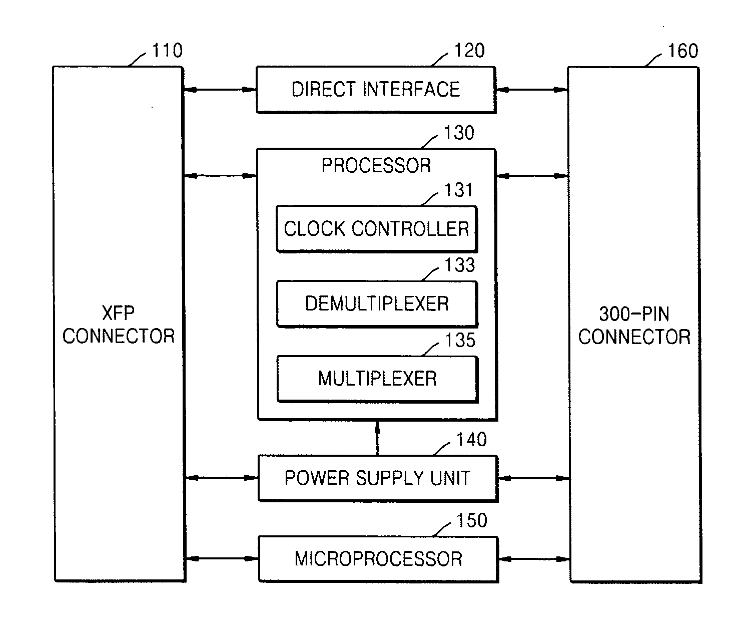
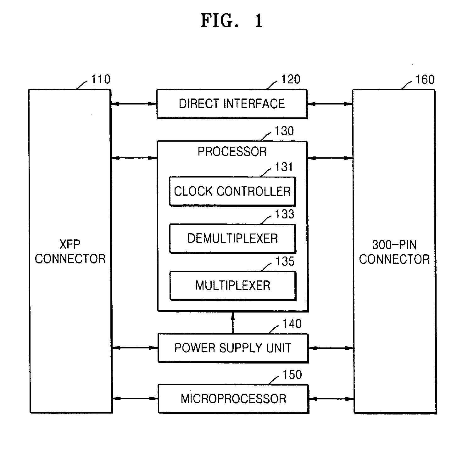
[0025] In general, since a 300-pin MSA optical transponder has 300 signal definitions, and an XFP optical transceiver has 30 signal definitions, interface functions are required for a proper interface between the two. The interface functions must include a signal demultiplexing function, a signal multiplexing function, a microprocessor function, a power re-supplying function, and an interfacing function between two different signal standards.

[0026] Therefore, the functions suggested in the present invention must be included to perform proper interfacing between two standards. This will be described with reference to the attached drawings. An XFP connector 110 illustrated in FIG. 1 indicates an XFP optical transceiver, and a 300-pin connector 160 indicates a 300-pin MSA optical transponder.

[0027] Referring to FIGS. 1 and 7, an ap...


PUM


Abstract

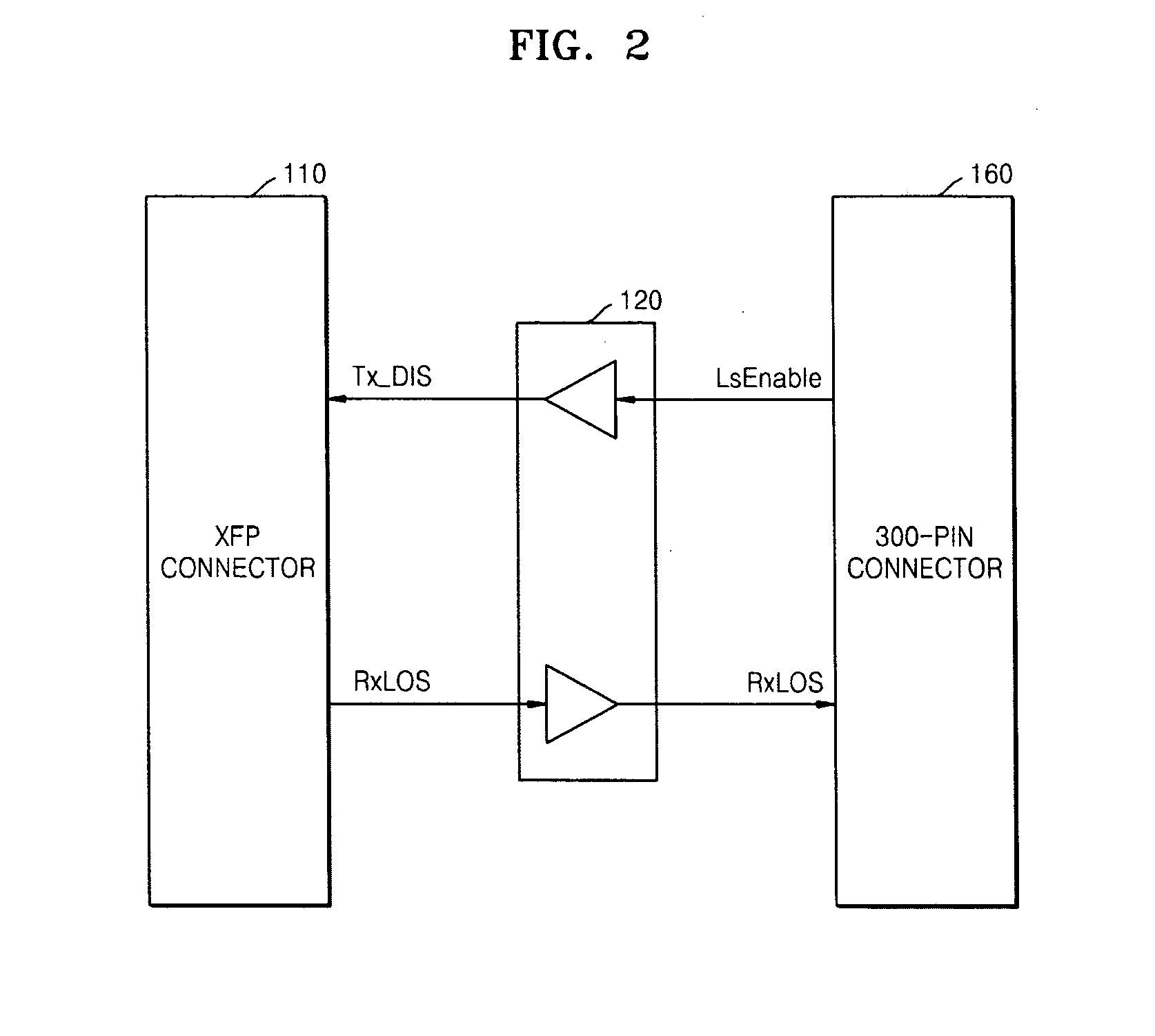
Provided are an apparatus and a method for interfacing a 10 Gbps small form factor pluggable (XFP) optical transceiver with a 300-pin multi-source agreement (MSA)_optical transceiver. The apparatus includes: a direct interface providing direct interfacing paths through which signals that can be directly interfaced with one another between the XFP optical transceiver and the 300-pin MSA optical transponder; and a processor converting clock signals and data between the XFP optical transceiver and the 300-pin MSA optical transponder so that formats of the clock signals and the data coincide with one another.

Description

CROSS-REFERENCE TO RELATED PATENT APPLICATION [0001] This application claims the benefits of Korean Patent Application No. 10-2005-0120108, filed on Dec. 8, 2005, and Korean Patent Application No. 10-2006-0071653, filed on Jul. 28, 2006 in the Korean Intellectual Property Office, the disclosures of which are incorporated herein in their entirety by reference. BACKGROUND OF THE INVENTION [0002] 1. Field of the Invention [0003] The present invention relates to an apparatus and a method for interfacing a 10 Gbps small form factor pluggable (XFP) optical transceiver with a 300-pin multi-source agreement (MSA) optical transponder in an optical transmitting system. [0004] 2. Description of the Related Art [0005] 300-pin multi-source agreement (MSA) optical transponders are generally used for long distance transmission, but have also been used for short-distance transmission with the rapid development of 10 Gbps small form factor pluggable (XFP) technologies. However, optical transponders ...

Claims


Application Information

Patent Timeline
Patent Type & Authority Applications(United States)
IPC IPC(8): H01R13/62
CPCH04J3/0685H04L7/0008
Inventor MYONG, SEUNG ILLEE, JYUNG CHANLEE, JONG HYUN
Owner ELECTRONICS & TELECOMM RES INST
Learn More