Al technical title is built by PatSnap Al team. It summarizes the technical point description of the patent document.
a technology of evacuator and discharge pipe, which is applied in the field of discharge pipe system, can solve the problems of clogging of exit port, entry or exit port, drain, etc., and the diameter of the exit port passage is typically 3 millimeters or less
Inactive Publication Date: 2007-06-07
SCOTTSDALE MEDICAL DEVICES
View PDF34 Cites 14 Cited by
Summary
Abstract
Description
Claims
Application Information
AI Technical Summary
This helps you quickly interpret patents by identifying the three key elements:
Problems solved by technology
Method used
Benefits of technology
Problems solved by technology
There are a number of problems with such evacuator systems, particularly related to clogging.
One problem is that either the drain, the conduit, the entry port or exit port may clog.
Another problem with such evacuator systems is that the diameter of the passage of the exit port is also typically 3 millimeters or less.
Consequently, when it is desirable to expel the fluid from the fluid container, due to the narrow diameter of the exit port it may clog and create difficulties in draining and / or increase the time to drain the fluid container.
Yet another problem with such evacuator systems is their limited volumetric capacity.
Still another problem with such evacuator systems is their use of valves, such as duck-bill-type valves, on the entry port passage through which fluid enters the internal reservoir of the fluid container.
Known designs, however, have such a small opening for allowing fluid to enter the reservoir that they tend to clog.
When in use, such valves may become clogged, rendering the system ineffective until the clog is removed.
Method used
Image
Click on the blue label to locate the original text in one second.
Reading with bidirectional positioning of images and text.
Examples
Embodiment Construction
[0022] Reference will now be made to the exemplary embodiments of the invention, which are illustrated in the accompanying drawings.
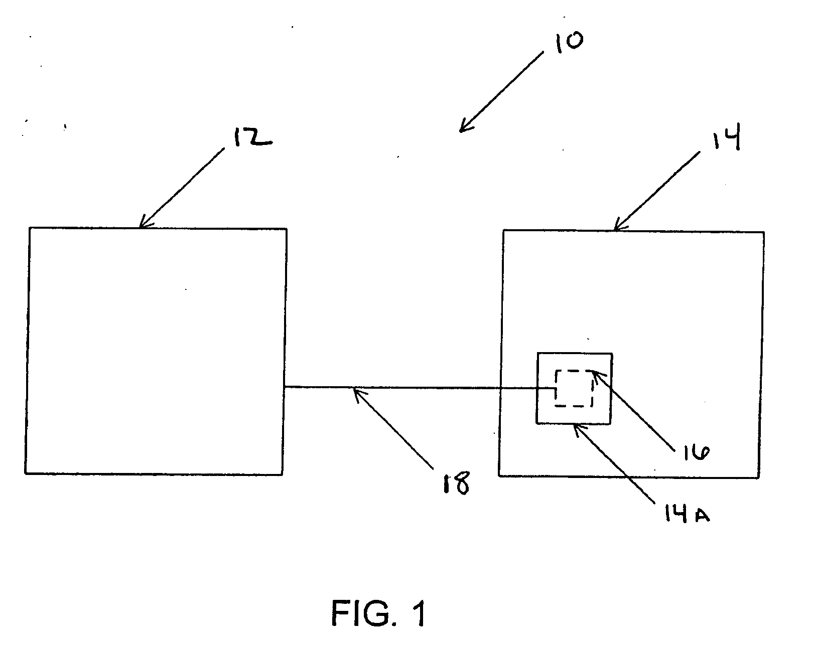
[0023] Referring to FIG. 1, an evacuator system 10 is shown for treatment of a patient 14 having a wound (or wound site) 14A. System 10 includes a fluid container 12, and may further include a drain 16 and a conduit 18. Drain 16 is shown in dashed lines to signify that it may be covered by surgical closure of wound site 14A, preferably, but not necessarily, creating an airtight seal for drain 16 within wound site 14A. Conduit 18 may be connected to drain 16 before wound site 14A is closed, so conduit 18 may extend outside wound site 14A and be connected to fluid container 12.
[0024] Drain 16 receives body fluid from patient 14. Any structure suitable for this purpose may be employed. In one embodiment, drain 16 may comprise a drain with a lumen having a diameter above 3 millimeters, such as the drain available from J.S. Vascular of Scottsdale, Ariz. an...
PUM
Abstract
A device is delineated for removing body fluid from a wound site. The device may include a drain sealed within the wound site, a conduit connected to the drain and a fluid container connected to the other end of the conduit. The fluid container may include at least one inlet passage of larger diameter to reduce likelihood of clogging during body-fluid inflow. An additional inlet passage may be included. The fluid container may also include at least one outlet passage of larger diameter to improve draining efficiency.
Description
RELATED APPLICATIONS [0001] This application is a continuation of and claims priority to U.S. patent application Ser. No. 10 / 863,009, filed Jun. 7, 2004, which claims the benefit of U.S. Provisional Application Ser. No. 60 / 476,663, filed Jun. 5, 2003 and U.S. Provisional Application Ser. No. 60 / 539,158, filed Jan. 26, 2004, and is a continuation of U.S. patent application Ser. No. 10 / 559,400, filed May 25, 2006, which is the National Stage of International Application No. PCT / US04 / 18134, filed on Jun. 7, 2004, which claims the benefit of U.S. Provisional Application Ser. No. 60 / 476,663, filed Jun. 5, 2003 and U.S. Provisional Application Ser. No. 60 / 539,158, filed Jan. 26, 2004, the disclosures of which are hereby incorporated by reference in the entirety for all purposes.FIELD OF THE INVENTION [0002] The present invention relates to a device and system for removing fluid from a wound on a patient. BACKGROUND OF THE INVENTION [0003] After a surgical procedure, body fluid may tend to...
Claims
Application Information
Patent Timeline
Application Date:The date an application was filed.
Publication Date:The date a patent or application was officially published.
First Publication Date:The earliest publication date of a patent with the same application number.
Issue Date:Publication date of the patent grant document.
PCT Entry Date:The Entry date of PCT National Phase.
Estimated Expiry Date:The statutory expiry date of a patent right according to the Patent Law, and it is the longest term of protection that the patent right can achieve without the termination of the patent right due to other reasons(Term extension factor has been taken into account ).
Invalid Date:Actual expiry date is based on effective date or publication date of legal transaction data of invalid patent.
Patent Type & Authority Applications(United States)