
Endless track belt

a technology of rubber track belts and end caps, which is applied in endless track vehicles, mechanical equipment, transportation and packaging, etc., can solve the problems of internal lug stress, surface wear at the points of contact, and severe wear of inner lugs

Inactive Publication Date: 2007-06-07
VEYANCE TECH
View PDF16 Cites 46 Cited by
  • Summary
  • Abstract
  • Description
  • Claims
  • Application Information

AI Technical Summary

Benefits of technology

[0004] The invention provides in a first aspect an endless rubber track belt comprising a rubber carcass having an inner surface having one or more guide-d...

Problems solved by technology

The continued use and contact between the drive bar and drive lugs cause internal lug stresses, and surface wear at the points of contact.
This contact can cause wearing of the inner lugs which can be severe depending upon various vehicle design features and usage applications.
Driving and / or guiding forces on the inner lugs, henceforth referred to as guide-drive lugs, can lead to eventual chunking of the rubber surface and possibly to complete removal of the drive lugs, making the track unserviceable.

Method used


Image

  • Endless track belt
  • Endless track belt
  • Endless track belt

Examples


Embodiment Construction

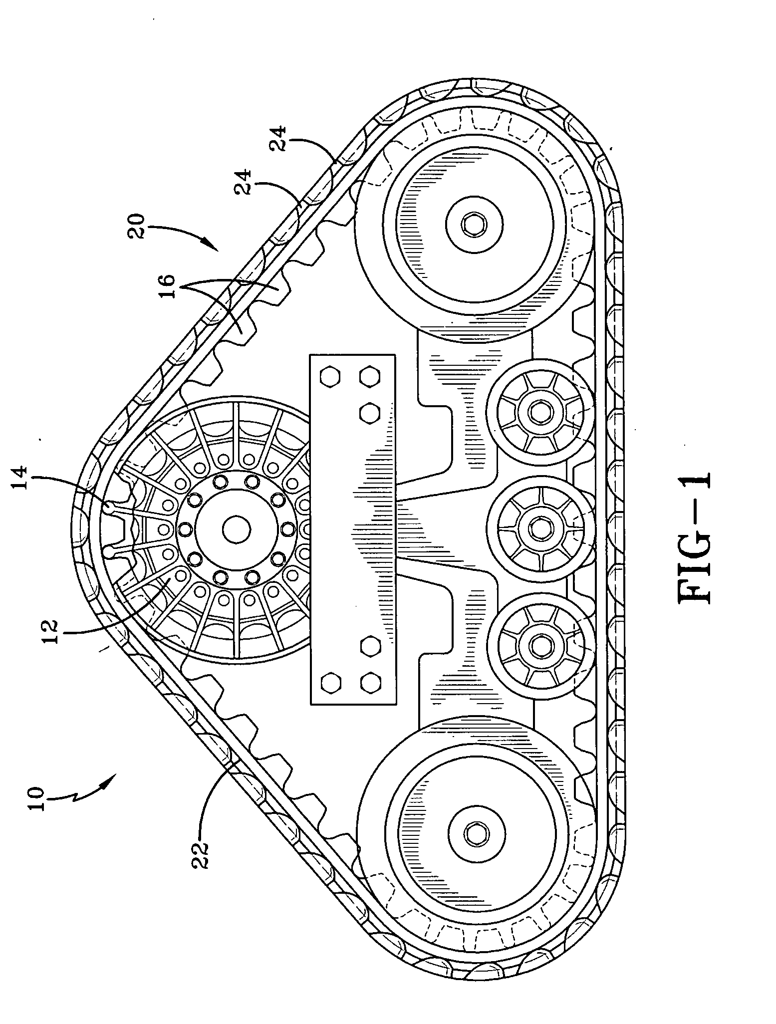
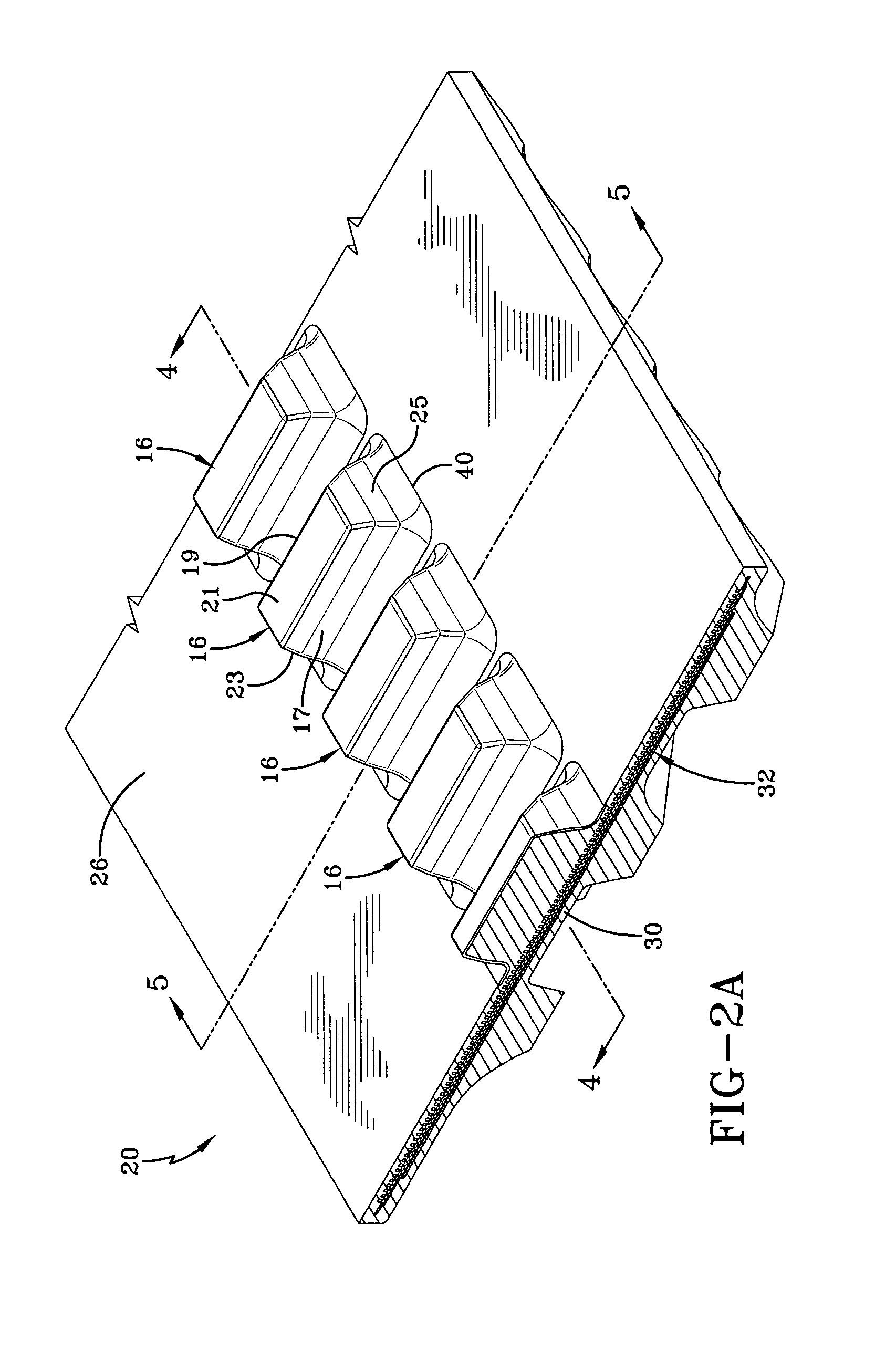
[0010]FIG. 1 illustrates a track assembly 10 which may be used on an industrial or agricultural vehicle (not shown). The track assembly 10 includes a drive wheel 12 comprising a plurality of teeth or drive bars 14 which are positioned for mating engagement with guide-drive lugs 16. The drive lugs 16 are mounted on a rubber track 20 having an endless elongate carcass. The endless track carcass has an outer surface 22 comprising a plurality of ground engaging tread lugs 24 and an inner surface 26 with a plurality of guide-drive lugs 16, typically located on the center portion of the carcass.

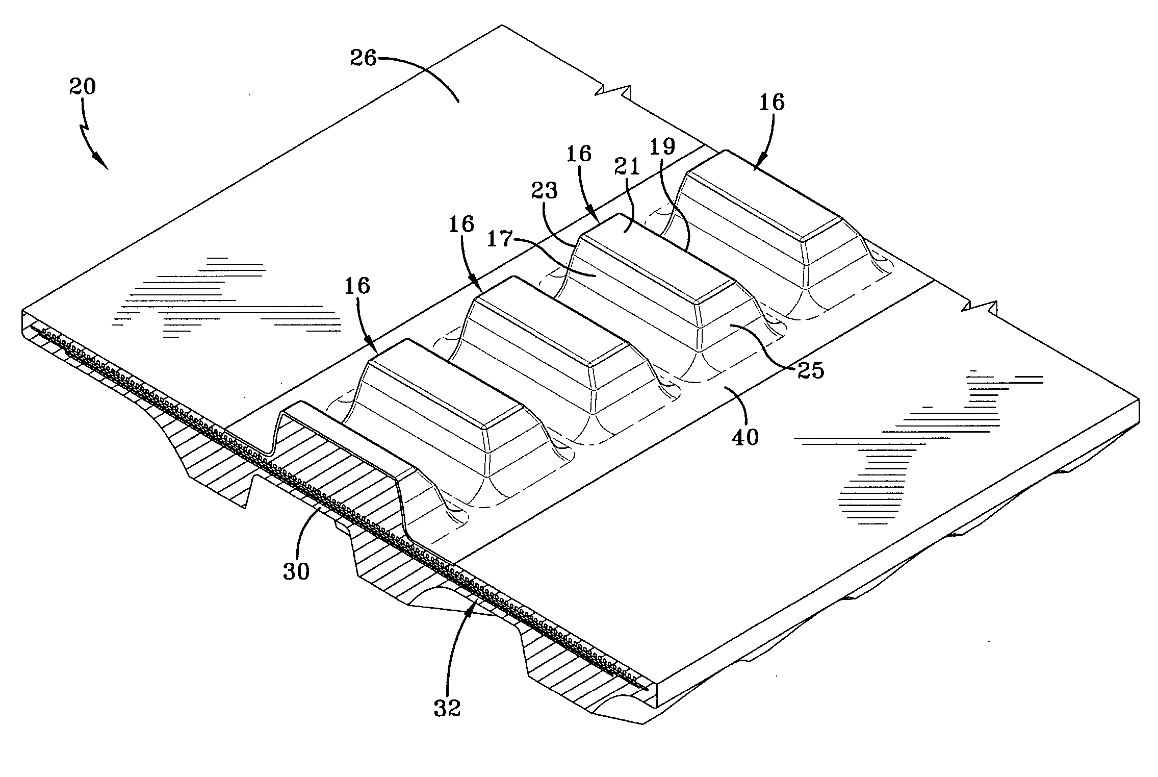
[0011] The guide-drive lugs 16 as shown in FIG. 3 comprise an elongate shaped bar with inclined drive faces 17, 19 and an upper flat face 21. The comers of the joined faces are rounded to reduce stress concentrations. Guide faces 23, 25 are also flat. The guide-drive lugs may also have various other shapes.

[0012] As shown in FIG. 2, the belt carcass 20 typically comprises one or more layers of gu...


PUM


Abstract

An endless track belt for use in an industrial or agricultural vehicle is described. The endless rubber track belt comprises a rubber carcass having an inner surface having one or more drive lugs and an outer surface having tread lugs, the drive lugs having a reinforcement layer of low friction material which extends substantially along the width of the drive lug. The low friction reinforcement material may also optionally extend substantially along the width of the track belt.

Description

[0001] This application claims the benefit of U.S. Provisional Application No. 60 / 741,951 filed Dec. 2, 2005.FIELD OF THE INVENTION [0002] This invention relates to endless rubber track belts. BACKGROUND OF THE INVENTION [0003] Rubber endless tracks such as for use on agricultural or industrial vehicles typically have an internal center ribbon of individual lugs which engage drive bars on a drive wheel. The continued use and contact between the drive bar and drive lugs cause internal lug stresses, and surface wear at the points of contact. Additionally, the internal center ribbon of lugs are typically functioning not only to transmit power from the drive wheel to the track, but also to retain the track onto the vehicle. Contact between the vehicle undercarriage wheels and the longitudinal or guide surfaces of the inner lugs frequently occurs as the vehicle maneuvers during normal service. This contact can cause wearing of the inner lugs which can be severe depending upon various veh...

Claims


Application Information

Patent Timeline
IPC IPC(8): B62D55/24
CPCB62D55/244
Inventor FELDMANN, THOMAS BRIANPETERSON, PAUL JOHNFOLK, KATHERINE ANNSCHISLER, ROBERT CHARLES
Owner VEYANCE TECH
Learn More