Al technical title is built by PatSnap Al team. It summarizes the technical point description of the patent document.
a printing system and color marking technology, applied in the field of printing systems, can solve the problems increasing mechanical complexity, and high cost of producing black prints on color marking engines, and achieve the effects of increasing mechanical complexity, higher cost, and increasing the cost of producing black prints
Inactive Publication Date: 2007-05-31
XEROX CORP
View PDF66 Cites 20 Cited by
Summary
Abstract
Description
Claims
Application Information
AI Technical Summary
This helps you quickly interpret patents by identifying the three key elements:
Problems solved by technology
Method used
Benefits of technology
[0017] In such machines, color marking engines which print with cyan, magenta, and yellow (CMY) as well as black (K) toners allow printing of both process color and black images on a single marking engine. However, the cost of producing black prints on a color marking engine is often higher than for a dedicated monochrome device. One reason for this is that the color components are often cycled, even during black printing. Although in some systems, the color components can be disabled during the production of monochrome prints, this tends to increase mechanical complexity to provide for retraction of the color components and to disengage their drives. Another reason for the higher cost is that the marking engine may provide a certain interdocument color toner throughput to control toner age in the system.
Problems solved by technology
However, the cost of producing black prints on a color marking engine is often higher than for a dedicated monochrome device.
Although in some systems, the color components can be disabled during the production of monochrome prints, this tends to increase mechanical complexity to provide for retraction of the color components and to disengage their drives.
Method used
Image
Click on the blue label to locate the original text in one second.
Reading with bidirectional positioning of images and text.
Examples
Embodiment Construction
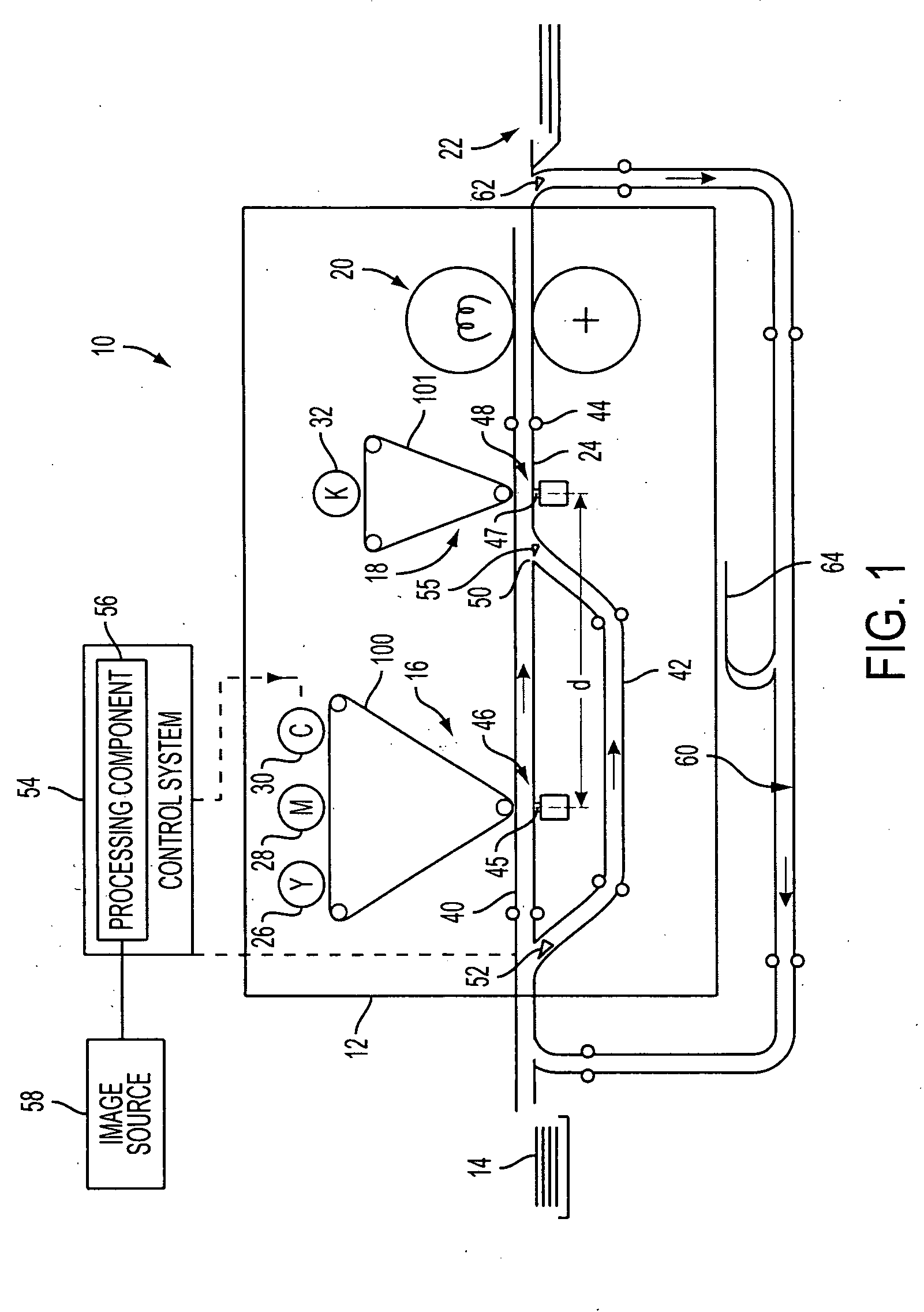
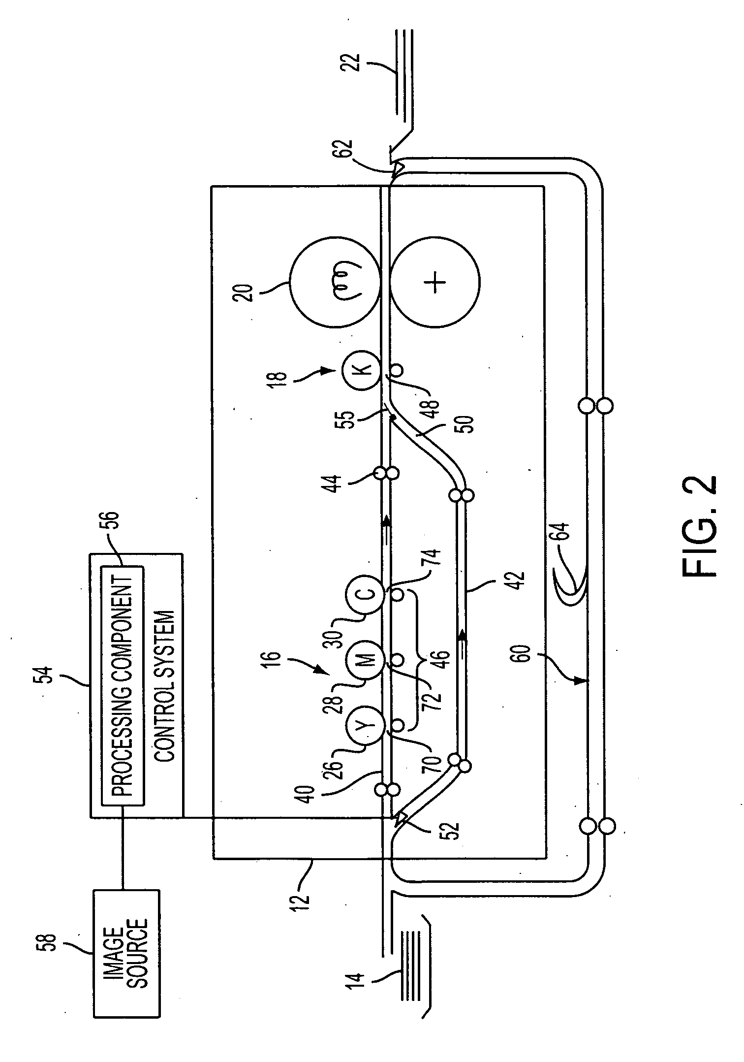
[0028] Aspects of the exemplary embodiment, as disclosed herein, relate to a marking engine for a xerographic printing system which is capable of both monochrome (e.g., black) and process color printing and to a method of printing.
[0029] The term “marking engine” generally refers to a device for applying an image to print media. The exemplary printing system may include one or more marking engines and a variety of other components, such as finishers, paper feeders, and the like, and may be embodied as a copier, printer, bookmaking machine, facsimile machine, or a multifunction machine. “Print media” can be a usually flimsy physical sheet of paper, plastic, or other suitable physical print media substrate for images. A “print job” or “document” is normally a set of related sheets, usually one or more collated copy sets copied from a set of original print job sheets or electronic document page images, from a particular user, or otherwise related. An image generally may include inform...
PUM
Abstract
A printing system includes a first image applying component configured for applying one or more primary colorants to print media for rendering an image. A second image applying component is configured for applying a second colorant, such as black colorant, to print media for rendering an image. A first pathway conveys print media between the first image applying component and the second image applying component. A second pathway bypasses the first image applying component for conveying print media which is printed by the second image applying component. Where an image is to be rendered With the primary colorants and optionally also black, the print media is directed on the first pathway to both the first and second image applying components. Where an image is to be rendered only with black colorant, the print media may be directed to the second image applying component via the bypass pathway. In this way, during black printing, the first image applying component can be placed in a standby mode.
Description
CROSS REFERENCE TO RELATED APPLICATIONS [0001] The following applications, the disclosures of each being totally incorporated herein by reference, are mentioned: [0002] Application Ser. No. 11 / 212,367 (Attorney Docket No. 20031830-US-NP), filed Aug. 26, 2005, entitled “PRINTING SYSTEM,” by David G. Anderson, et al., and claiming priority to U.S. Provisional Application Ser. No. 60 / 631,651, filed Nov. 30, 2004, entitled “TIGHTLY INTEGRATED PARALLEL PRINTING ARCHITECTURE MAKING USE OF COMBINED COLOR AND MONOCHROME ENGINES”; [0003] U.S. application Ser. No. 10 / 761,522 (Attorney Docket A2423-US-NP), filed Jan. 21, 2004, entitled “HIGH RATE PRINT MERGING AND FINISHING SYSTEM FOR PARALLEL PRINTING,” by Barry P. Mandel, et al.; [0004] U.S. application Ser. No. 10 / 881,619 (Attorney Docket A0723-US-NP), filed Jun. 30, 2004, entitled “FLEXIBLE PAPER PATH USING MULTIDIRECTIONAL PATH MODULES,” by Daniel G. Bobrow; [0005] U.S. application Ser. No. 10 / 917,768 (Attorney Docket 20040184-US-NP), fil...
Claims
Application Information
Patent Timeline
Application Date:The date an application was filed.
Publication Date:The date a patent or application was officially published.
First Publication Date:The earliest publication date of a patent with the same application number.
Issue Date:Publication date of the patent grant document.
PCT Entry Date:The Entry date of PCT National Phase.
Estimated Expiry Date:The statutory expiry date of a patent right according to the Patent Law, and it is the longest term of protection that the patent right can achieve without the termination of the patent right due to other reasons(Term extension factor has been taken into account ).
Invalid Date:Actual expiry date is based on effective date or publication date of legal transaction data of invalid patent.
Patent Type & Authority Applications(United States)