
Ceiling illumination for aircraft interiors

a ceiling illumination and interior technology, applied in the direction of mass transit vehicle lighting, landing aids, lighting support devices, etc., can solve the problems of claustrophobic and limited space in the passenger cabin of airplanes, and achieve the effect of improving the perception and aesthetics of the passenger space, improving the configuration, architecture, lighting and aesthetics of the passenger cabin, and improving the atmosphere and situation of the passenger

Active Publication Date: 2007-05-17
THE BOEING CO
View PDF11 Cites 62 Cited by
  • Summary
  • Abstract
  • Description
  • Claims
  • Application Information

AI Technical Summary

Benefits of technology

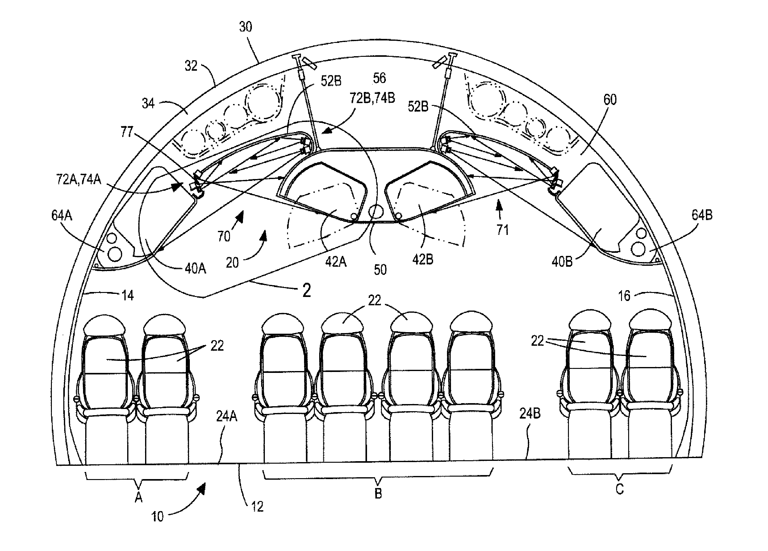
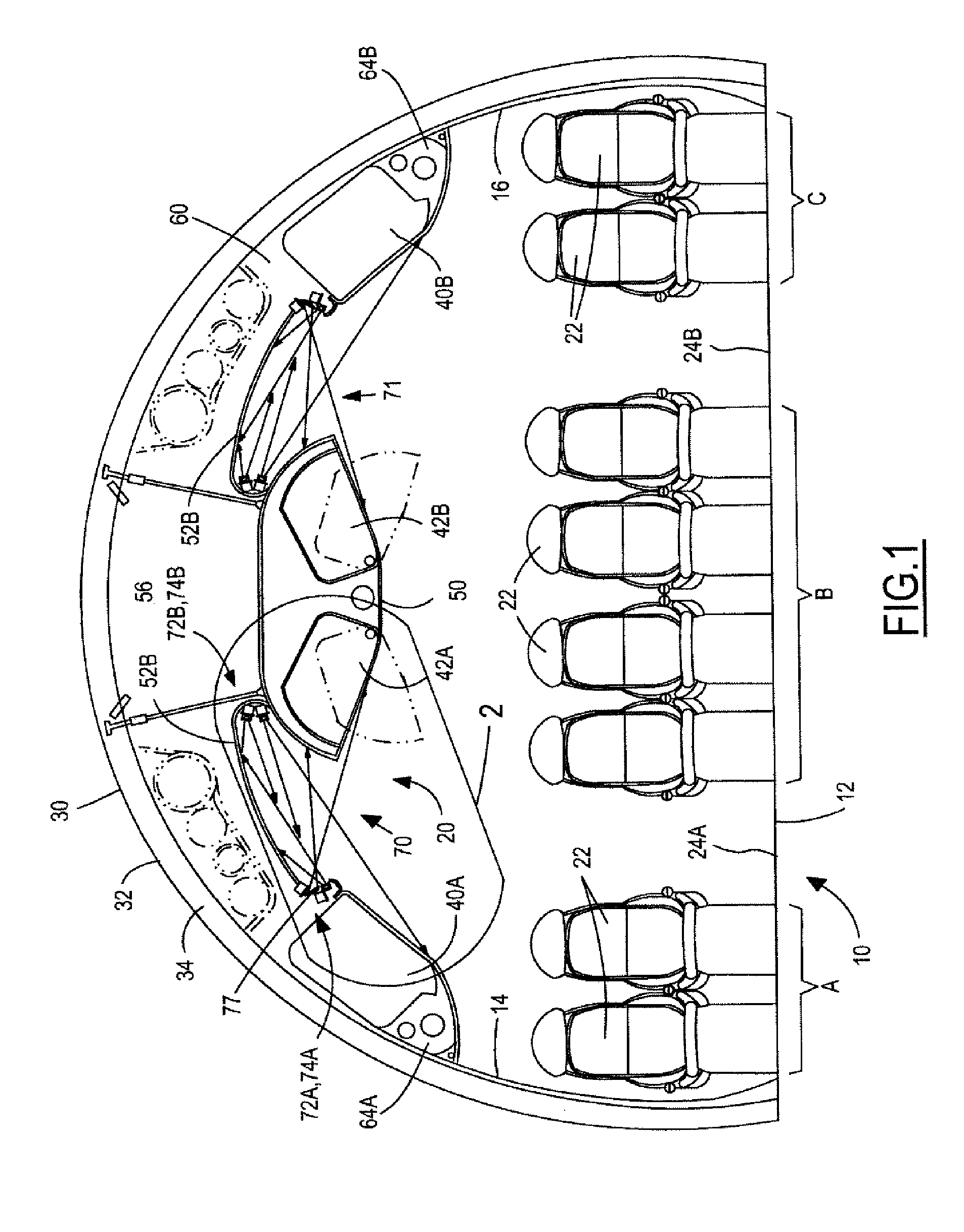
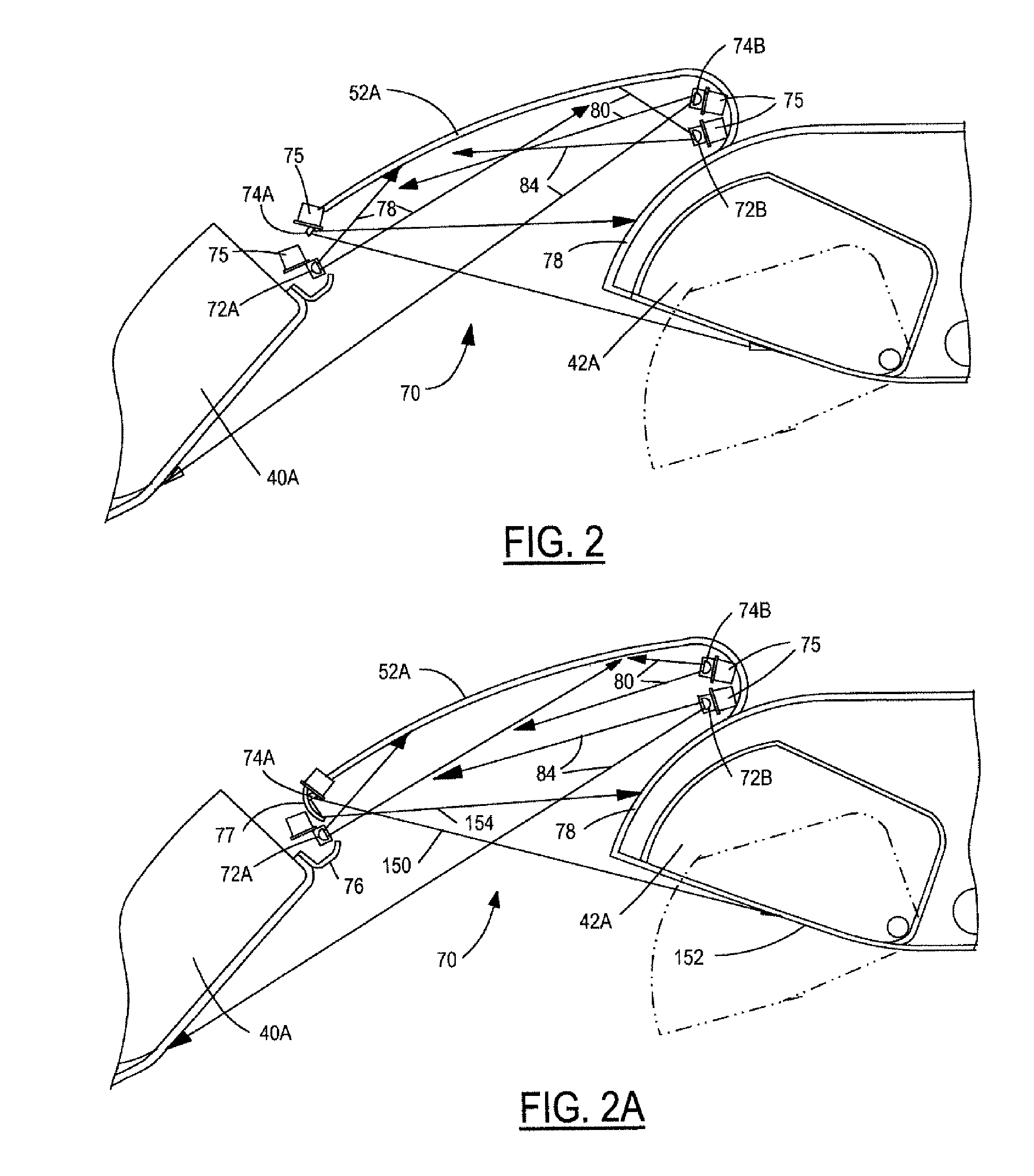
The present invention is about improving the configuration, architecture, illumination, and aesthetics of passenger cabins for airplanes. The invention provides LED lighting fixtures that provide color and illumination in a significantly different manner than with present airplanes and passenger cabins. The lighting fixtures are preferably positioned in various configurations, such as by being stacked one on top of the other, positioned individually side-by-side, or positioned in groups side by side. The lighting fixtures can be controlled to provide dynamic lighting or mood lighting based on the situation aboard the aircraft at the time. A deflector is utilized to direct the light across the ceiling spaces to the specific areas desired and reduce glare for the passengers. The light rays directed to the lowest part of the opposite storage / stowage bins are illuminated from light emanated from the top of the reflector. The invention ensures that none of the reflector is visible to the passengers.

Problems solved by technology

In general, the space in the passenger cabins in airplanes is limited and can be called claustrophobic at times. In this regard, the design, architecture, and lighting of the interiors of passenger aircraft, particularly the passenger cabins, have remained typically constant for a long period of time and have not had a significant variety of changes or updates as common in many industries.

Method used


Image

  • Ceiling illumination for aircraft interiors
  • Ceiling illumination for aircraft interiors
  • Ceiling illumination for aircraft interiors

Examples


Embodiment Construction

[0020] The passenger compartments of commercial airlines today have become relatively standardized and have not had a significant amount of innovation. The space itself in passenger cabins is quite limited due to the external size and configuration of the airplane itself and thus any changes are necessarily limited to begin with. However, with the present invention, the interest, ambience, and aeronautic quality of the space is enhanced and increased significantly. With the present invention, the illumination and lighting systems have been improved to change the passenger's perception of the passenger cabin, particularly the height and aesthetics of the ceiling.

[0021] In addition, different lighting techniques and the color of the lights can be changed in accordance with the present invention in order to cater to different moods of the passengers and also to change the “look and feel” of the passenger cabin during some of the key operations of the passenger airline experience, such...


PUM


Abstract

Interior lighting and illumination systems for aircraft, particularly commercial passenger airplanes. Opposing pairs of LED lamps are positioned in the ceiling panels above the aisles between sets of seats in the passenger cabins. One set of LED lights are directed to illuminate the ceiling panels and may be in a particular color. The other set of LED lights are positioned to shine their lights on storage / stowage bins positioned across the aisles, thus creating a cross-bin lighting system. This enhances the cabin architecture and provides cabin illumination. A reflector can be positioned to direct the light and reduce possible glare to the passengers. The reflector directs the light rays from the LED lights which emanate from the top of the reflector to shine on the lowest part of the bins. The light rays leaving the reflector cross in front of the reflector.

Description

TECHNICAL FIELD [0001] The present invention relates to interior illumination systems for aircraft, particularly interior illumination and lighting systems for the passenger cabins in commercial passenger airplanes. BACKGROUND OF THE INVENTION [0002] The interior configuration, architecture, and illumination of airplanes has become relatively standardized today. The arrangement of passenger seats, passenger cabins, bulkheads, lavatories, serving areas, and the like have become developed for convenience and accommodation of both passengers and crew. The passenger compartments have sidewall members with a plurality of windows, a floor member and a ceiling member or assembly of some type. In addition, pluralities of rows of stowage or storage bins are positioned on the aircraft generally at the position between the sidewalls and the ceilings. For larger twin-aisle aircraft, rows of inboard stowage bins are also positioned over the seats positioned along the center of the passenger cabi...

Claims


Application Information

Patent Timeline
Patent Type & Authority Applications(United States)
IPC IPC(8): B64D47/02F21S8/10B60Q3/06
CPCB64D11/00B64D11/003B64D2011/0038B60Q3/43
Inventor BRYAN, ERICCAMP, RANDOLPHFRAKER, RICHARDSHIMASAKI, KEVINWEBB, MILES
Owner THE BOEING CO
Learn More